 Get a quote
Resources
Tube Bend Quality After the First Sample: How to Check Wrinkles, Ovality and Wall Thinning
 JUGAO engineering brief
Tube forming / first-article inspection
Measure the bend.
Then approve the sample.
Wrinkles. Ovality. Remaining wall.
Turn the first sample into a repeatable inspection record.
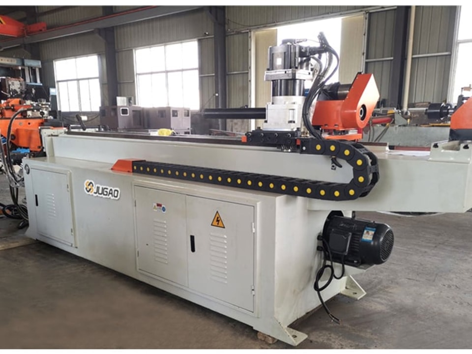
A first bent tube should not be released by visual inspection alone. Compare it with the drawing or customer-signed acceptance limits. At agreed locations, measure wrinkle depth, cross-section Dmax/Dmin, and minimum extrados wall thickness. Record the denominator, instrument and calibration status, material heat or lot, tooling, and setup conditions. Approve only after the first sample meets the plan and the agreed repeat samples meet their repeatability condition. One part is not proof of long-term process capability.
Freeze the acceptance plan before measuring
First-article inspection starts with a measurement plan, not a generic tolerance. Identify the drawing revision, part and sample ID, material and temper, heat or lot, nominal and incoming measured OD, nominal and measured incoming wall thickness, CLR, bend angle, seam orientation where applicable, and the source of each acceptance value.
For each characteristic, agree on the section, circumferential direction, part state, method, instrument, calibration status, equation, denominator or baseline, numeric limit, sample quantity, repeatability condition, and approval authority.
| Plan item | Question to freeze | Record before release |
|---|---|---|
| Geometry and station | Which bend, section, and start/middle/end station? | Part mark, station, bend-plane reference |
| Baseline | Nominal or same-lot measured OD/wall? | D0 or N; t0 and units |
| Method | Which instrument and measurement direction? | Instrument ID, calibration status, operator |
| Acceptance | Where does the limit come from? | Drawing, contract, code, or signed plan |
| Sampling | How many pieces and what repeatability condition? | Sample quantity, disposition, signatures |
Inspect three zones on the bend
Use the drawing-designated sections or positions agreed in the plan, such as the start, middle, and end of the bend. Mark the bend plane and circumferential direction so another operator can reproduce each reading.
| Bend zone | Inspection target | Record value | Do not infer |
|---|---|---|---|
| Intrados (inside radius) | Visible wrinkles, dents, location, count, and depth where required | Station, orientation, presence/count, depth method, depth/unit | “No obvious wrinkle” is not a numeric depth result |
| Extrados (outside radius) | Minimum remaining wall at agreed stations | t0, every reading, tmin, unit, thinning calculation if defined | Nominal wall is not automatically the measured baseline |
| Specified cross-section | Largest and smallest outside diameters | Section, directions, Dmax, Dmin, denominator, result | One-direction caliper reading is not Dmax/Dmin |
Wrinkles: separate visibility, location, count, and depth
Record whether a wrinkle is visible, where it occurs, how many are present, and its depth if the plan calls for it. NASA KSC-SPEC-Z-0008 illustrates wrinkle depth as the perpendicular distance from the trough bottom to an arc connecting adjacent wrinkle peaks. This is a measurement concept in a KSC-specific specification, not a default limit for every bent tube. NASA KSC-SPEC-Z-0008 Rev D Change 2.
Ovality: state the denominator
At each specified section, find the actual largest and smallest outside diameters and retain their directions. A documented form is:
Identify N. The NASA KSC/GSE example uses nominal OD, while research methods may use incoming measured OD. The drawing, contract, or signed plan must select the denominator.
Dmax · Dmin · denominator N or D₀
Wall thinning: define the baseline and retain thickness values
State whether t0 is nominal thickness or a same-lot measured incoming baseline. tmin is the minimum measured thickness at the agreed extrados locations. Report both values with units even when a percentage is required. If the acceptance criterion is minimum remaining wall, judge tmin separately.
t₁Middle
t₂End
t₃
ASTM E797/E797M-21 covers manual ultrasonic pulse-echo contact thickness measurement from one side; the official page lists an upper temperature limit of 93°C and requires a material that supports stable sound transmission and a readable back-wall echo. It defines a measurement method, not an acceptance limit for ovality, wrinkles, or thinning. Before measuring a thin curved wall, confirm the probe, calibration block, material sound velocity, surface, curvature, coupling, and required measurement capability on the actual part. ASTM E797/E797M official scope.
Put every acceptance limit beside its source
No single tolerance safely applies to every tube bend. Use the part drawing, contract, end use and applicable specification, or a written first-article plan agreed by customer and supplier.
| Acceptance source | What it controls | What to record | Boundary |
|---|---|---|---|
| Part drawing/customer specification | Actual part dimensions and stated defect limits | Revision, clause, characteristic, value | Applies to the identified part and revision |
| Contract/applicable industry code | Approved scope and engineering requirements | Code edition, component scope, approval | Do not infer a limit from a public scope summary |
| Signed first-article plan | Method, station, denominator, sample count, sign-off | Plan ID, signatures, date | Project-specific agreement |
| NASA KSC-SPEC-Z-0008 Rev D Change 2 | KSC/GSE-specific flatness and wrinkle example | Scope and size condition beside each number | Not a universal commercial default |
| Vendor case study | Reported customer/application example | Source, sample, material, context | Not a standard or JUGAO guarantee |
NASA KSC/GSE example—keep the scope attached
NASA KSC-SPEC-Z-0008 Revision D Change 2 covers fabrication and installation of 37° flared tube assemblies and fittings in KSC fluid-pressure systems; KSC engineering approval is required and the specification is mandatory for its KSC use. Its GSE tube provision gives a flatness/ovality index F = (Dmax − Dmin) / N × 100 with F ≤ 5%, where N is nominal OD. For wrinkle depth, it lists a maximum of 2% of OD when OD ≤ 3/4 in and 1% of OD when OD ≥ 1 in. The source gives no rule for the interval above 3/4 in and below 1 in, so do not interpolate. It also gives no general post-bend wall-thinning limit. These are KSC/GSE-specific terms, not universal commercial tube-bend tolerances. NASA KSC-SPEC-Z-0008 Rev D Change 2.
denominator: nominal OD N
ASME B31.3 is relevant only when the component falls within its process-piping scope and the contract or engineering authority specifies the applicable code and edition. Its public scope page is not a basis for inventing tube-bend ovality, wrinkle, or thinning limits. ASME scope
What one bending study can—and cannot—tell you
The peer-reviewed rotary draw-bending study by Bahadır Ozcan, Zafer Evis, and Fahrettin Ozturk is recorded by Istanbul Technical University and summarized in the SAGE journal abstract. It studied AA6061-W (“water condition”) tube with OD 50.8 mm, initial wall thickness 0.889 mm, and bend radius 101.6 mm (twice this specimen’s OD), comparing five mandrel positions. The public abstract reports ovality of 0.83%–1.81% and minimum extrados wall thickness of 0.686 mm; results varied with mandrel position. The material state and this geometry bound the finding.
| Reported item | Value | How to use it |
|---|---|---|
| Material/state | AA6061-W, “water condition” | Keep the material/state attached to every comparison |
| Tube geometry | OD 50.8 mm; initial WT 0.889 mm; CLR 101.6 mm | Describes this study’s test geometry only |
| Mandrel variable | Five positions compared | Shows a process variable can affect multiple outcomes |
| Ovality | 0.83%–1.81% | Abstract-reported range, not an acceptance limit |
| Minimum extrados wall | 0.686 mm | Abstract-reported thickness, not a JUGAO guarantee |
Calculated from the abstract’s thickness values; not directly reported by the authors’ abstract.
The public abstract does not state the bend angle, specimen count, ovality equation, or complete tooling details. This single material/geometry study is not JUGAO test data, a universal threshold, or a recommended setup value.
A separate Schwarze-Robitec/TDM aircraft case reports titanium tube walls of 0.56–0.88 mm, ovality below 3%, parts with up to 16 bends, and an initial acceptance test using 10 selected pieces at the Cologne factory. That is a customer-specific preliminary test described by a competing supplier, not a JUGAO machine capability, tolerance, or guarantee.
Tooling is a system of interacting variables
BLM GROUP relates bend-die groove selection to CLR/OD and describes the pressure die and wiper die as supporting the tube shape, with the wiper near the intrados helping control wrinkles or bulges. A mandrel is selected to fit the tube ID and supports the tube internally. Tooling fit and the result still depend on the tube, die set, alignment, and process conditions. Clamping, boost/feed, mandrel head and extension, lubrication, speed, and material lot may also influence the result; a mandrel or wiper does not automatically remove wrinkles or ovality. BLM GROUP tooling overview.
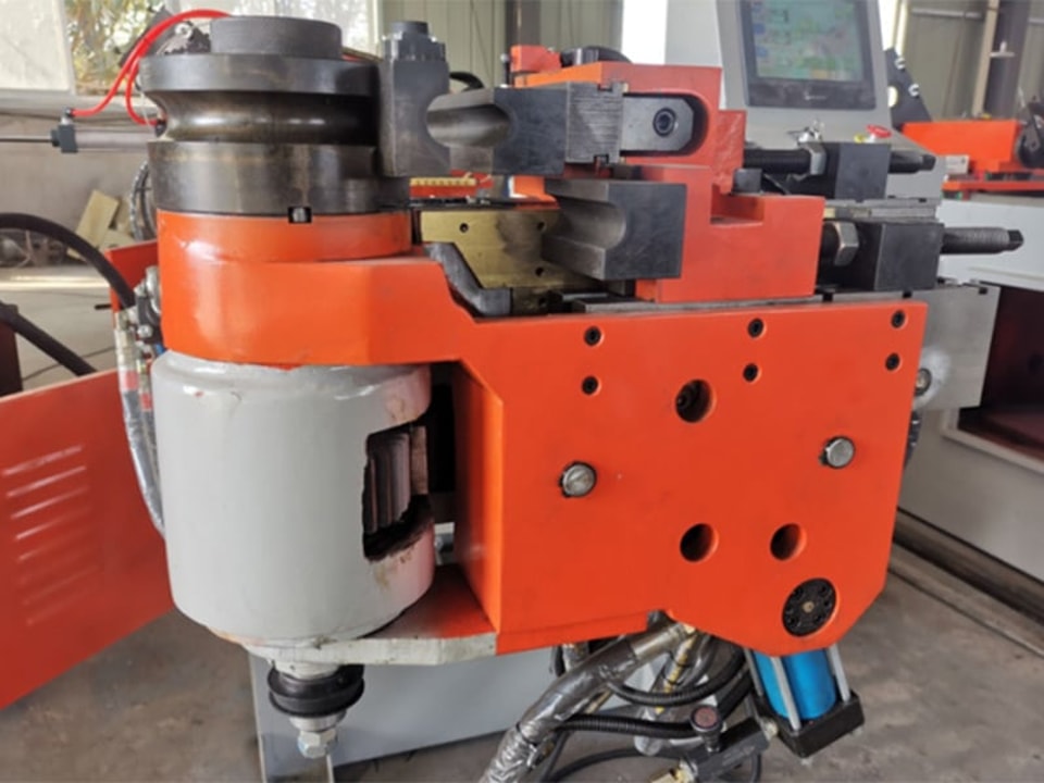
First-article inspection record
Copy or screenshot the following record structure and add rows for every bend and measurement station. Record raw readings before calculating a result.
| Record field | Entry / evidence |
|---|---|
| Drawing revision; part number; sample ID | ________________________________________ |
| Material, grade/condition, heat or lot | ________________________________________ |
| OD: nominal / incoming measured | ________________________________________ |
| Wall thickness: nominal / incoming baseline | ________________________________________ |
| Seam orientation, if applicable | ________________________________________ |
| CLR; bend angle; sample quantity | ________________________________________ |
| Bender ID; program/version | ________________________________________ |
| Bend/clamp/pressure die IDs | ________________________________________ |
| Mandrel/wiper IDs; mandrel extension | ________________________________________ |
| Pressure; boost/feed; speed; lubrication | ________________________________________ |
| Station and circumferential direction | ________________________________________ |
| Wrinkle visibility, location/count, depth method | ________________________________________ |
| Dmax; Dmin; denominator; calculated ovality | ________________________________________ |
| t0; tmin; units; calculated thinning | ________________________________________ |
| Instrument model; calibration status/date | ________________________________________ |
| Raw results; repeatability decision; disposition | ________________________________________ |
| Operator; customer/quality sign-off; date | ________________________________________ |
A conforming single sample supports only the first-piece decision defined by the plan. Repeat samples address repeatability under specified conditions. Long-term process capability requires separate production evidence and must not be claimed from a first sample.
Frequently asked questions
Can a first bent tube be approved by visual inspection?
Not when the plan includes wrinkles, ovality, or remaining wall thickness. Record locations, method, readings, and acceptance source.
Where should the bend be measured?
Use drawing-designated sections or agreed start, middle, and end stations. Mark the bend plane and circumferential direction.
Is there a universal ovality limit?
No. Use the drawing, contract, applicable specification, or signed customer/supplier plan.
Does NASA’s 5% value apply to all commercial tube bends?
No. It is a KSC/GSE-specific example. Its wrinkle-depth values are tied to stated size conditions, and the cited passage gives no rule for the interval above 3/4 in and below 1 in.
Is ultrasonic measurement automatically suitable on a thin curved tube?
No. Confirm probe, calibration, material sound velocity, surface, curvature, coupling, and setup capability on the actual part.
Will a mandrel always remove wrinkles or ovality?
No. Verify the actual sample after considering wiper and pressure dies, alignment, extension, feed/boost, lubrication, speed, material condition, and geometry.
Does one accepted sample prove production capability?
No. Keep first-piece conformance, repeatability, and long-term capability as separate conclusions.
What if the drawing has no acceptance value?
Pause release and obtain written agreement on characteristic, location, method, denominator, limit, sample quantity, and sign-off authority.
JUGAO resources and part-specific inquiry
The JUGAO ER-63 CNC product page lists “3 Axis / Full Automatic,” maximum bending capacity 63 × 4 mm, a 20–300 mm bending-radius range, minimum radius R ≥ 1.4D, a 0–190° angle range, and one set of standard dies. The angle row’s unit column says “mm,” which conflicts with the degree values. The description says rotation and feeding use two servos; the configuration table lists Delta CNC, Omron PLC, and Mitsubishi rotation/feed servos, while a bending servo and 3D controller are optional. The page also describes manual, semi-automatic, and full-automatic modes. It does not explain how “3 Axis” relates to the two described servos and optional bending servo. The material grade/state, wall thickness, tooling conditions, and whether the published capacity and radius values can be met simultaneously are not stated; neither is the definition of D in R ≥ 1.4D. Ask JUGAO to confirm the required material, wall, tooling, and configuration for the part.
The same page gives an “Effective Length Over Mandrel” of 4000 mm and a feed stroke of 3000 mm, without defining their relationship or the configuration they require. It also lists maximum pressure as “160 Kg/cm” (an incomplete unit) and separately lists hydraulic-system working pressure as 16 MPa; their relationship is not stated, so neither figure should be silently converted or treated as equivalent. The standard die set is not itemized. Do not transfer mandrel or wiper-die options from the separate ER-63 NC page to the CNC model.
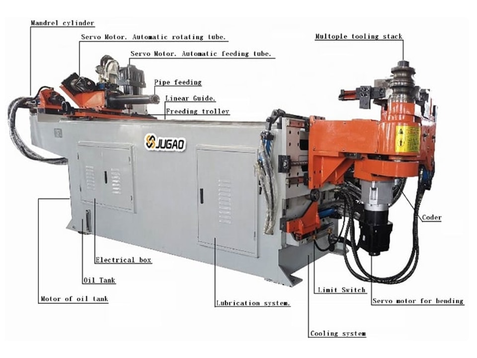
If you are preparing the machine, read JUGAO’s trial-production and installation-check article for adjacent setup context. For operating symptoms that need further troubleshooting, see Common Problems in the Operation of Pipe Bending Machines. These links complement, but do not replace, the sample-measurement plan.
For a part-specific discussion, contact JUGAO with the drawing revision, material and lot, OD, wall thickness, CLR, bend angle, required acceptance values, sample quantity, and preferred measurement method.
Sources
- Ozcan, Evis, and Ozturk, “Effect of mandrel position on bending quality in the rotary draw bending process,” SAGE journal abstract.
- Istanbul Technical University research record for the paper.
- NASA KSC-SPEC-Z-0008, Revision D, Change 2.
- ASTM E797/E797M official page.
- BLM GROUP bending tool management overview.
- Schwarze-Robitec/TDM aircraft tube-bending case.
- ASME B31.3 process-piping scope page.
- JUGAO ER-63 CNC hydraulic pipe bending machine product page.
© 2026 JUGAO. All rights reserved. Except for materials credited to third parties, the original text, graphics and design of this article are owned by JUGAO. Unauthorized reproduction or redistribution is prohibited.
Related
Keep
reading.
 Comparison of Laser Welding Results and Application Scenarios Across Different Materials
 How to Choose Between Air-Cooled and Water-Cooled Laser Welding Systems
 Understanding Punching Machines: Principles, Types, and Selection
 How can one effectively follow the installation guidelines for a pipe-bending machine?
 Can Your Plate Roll Form This Cone? A Drawing-to-Sample Buying Checklist
 For which types of products is an automatic wire-feeding laser welding machine suitable?
 What Are the Latest Punching Machine Trends and Technological Breakthroughs?
 What Triggers Punching Machine Noise and How Can You Quieten It?
 What factors influence the replacement cycle of wear parts in a pipe-bending machine?
 Beyond price, what key parameters should you consider when purchasing welding equipment?
 4 Common Methods for Inspecting Weld Quality
 Selecting the Top Punching Machines for Small Workshops & Heavy Industry
Engineering review
Send a drawing.
Get an engineer.
Standard selections answered within 4 hours. Parts outside the rules get a written process review within 24 hours.
- Part drawing: DXF, DWG, STEP or PDF
- Material and thickness
- Longest bend or cut length
- Yearly volume
Write to info@ntjugao.com or message the factory on WhatsApp +86 132 2211 1178.
Drawings (DXF, DWG, STEP, PDF): attach them to an email to info@ntjugao.com, quoting your name.