
JUGAO Project Engineering Solutions: A Complete Technical and Engineering Solution, Not Just a Quote
2026-09-30


JUGAO Project Engineering Solutions
A complete technical and engineering solution, not just a quote.
For a JUGAO W12 four-roll plate rolling project, the engineering answer starts with material strength, plate thickness and axial width, finished inside or outside diameter, both-end pre-bending and allowable flat ends. The quotation should tie these to one written operating case, followed by an agreed sample and measurement plan.
Start with one combined operating case
A plate roll does not process “25 mm” in isolation. It processes a material with a specific yield and tensile response, across a specified width, into a specified curvature while the rolls, frame and hydraulic system react to the load. The first and second plate ends also have to be pre-bent close enough to the target curvature for the seam preparation and welding plan.
For W12 selection, the published model row is a useful starting point. The proposed plate, finished geometry, edge preparation and sample test must still be evaluated together before an order-specific engineering answer can accompany a price.
That is why a buyer should never combine the most favorable values from separate catalogue columns and treat the result as an acceptance guarantee. The useful question is: can this exact machine configuration roll and pre-bend this exact plate, over this axial width, to this defined finished diameter, with these flat-end and roundness requirements?
| Input group | Must be stated together |
|---|---|
| Material | Grade, actual yield and tensile properties, elongation and rolling direction |
| Plate | Measured thickness and full axial width through the rolls |
| Cylinder | Finished ID or OD, inspection stage, roundness and allowable flat ends |
| Machine and trial | Exact W12 configuration, supports, unloading path and sample method |
Define the cylinder before selecting the machine
Six dimensions are easily confused in a plate-roll enquiry. A drawing should identify the finished outside diameter Do, finished inside diameter Di, plate thickness t, mid-thickness diameter Dm, axial cylinder length or rolling width B, and the developed length running around the circumference. Width B and developed length are perpendicular dimensions; interchanging them can produce the wrong machine selection and the wrong blank.
What the four rolls do—and why pre-bending is separate
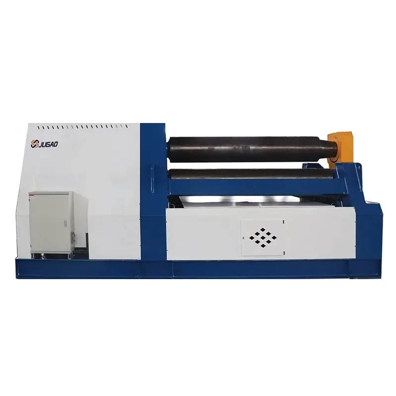
On the JUGAO W12 product page, the upper roll is described as the main driven roll, while the lower and side rolls move hydraulically. The upper and lower rolls clamp the plate; the side rolls establish the bending geometry; and a tilting bearing arrangement is listed for unloading the formed cylinder. These descriptions explain a process route, but they do not define the capacity of one ordered configuration under every material and diameter condition.[1]
Clamp
The upper and lower rolls grip and feed the plate. Confirm the material surface, plate alignment and permissible marking.
Bend and support
The active side roll, roll spacing, force, deflection and workpiece support all affect the developing curvature and flat ends.
Near each plate edge, the rolls cannot create exactly the same contact condition as in the central region. Pre-bending is therefore a distinct capacity question. The supplier should state the maximum pre-bending thickness for the combined case and the residual flat achievable at each end, including where that flat is measured. A main-rolling thickness is not automatically a two-end pre-bending thickness.
| Operation | What changes | Required acceptance field |
|---|---|---|
| Main rolling | Central plate length bends under the established contact geometry. | Thickness at material, width and target diameter |
| Pre-bend end A | Near-edge contact and lever arm differ from the central region. | End A residual flat and measured location |
| Pre-bend end B | The second edge is reversed or repositioned in the pass plan. | End B residual flat and measured location |
What the public JUGAO table says—and what it does not
The following values are transcribed from the JUGAO main-site W12 table. They are public page fields, not measurements from this project and not proof that every value in one row is simultaneously achievable for the same material, workpiece, two-end pre-bend and one-pass cycle.[1]
| Page model | Max roll thickness | Max roll width | Yield-strength field | Min roll diameter | Upper roll diameter |
|---|---|---|---|---|---|
| W12-25X2000 | 25 mm | 2000 mm | 245 MPa | 800 mm | 350 mm |
| W12-20X2500 | 20 mm | 2500 mm | 245 MPa | 640 mm | 350 mm |
| W12-25x2500 | 25 mm | 2500 mm | 245 MPa | 800 mm | 400 mm |
The page does not define whether the 245 MPa field is an exact reference value, a limit or another rating convention. It does not state tensile strength, elongation, grade or rolling direction. Nor does it define whether “Min roll diameter” means finished ID, OD, mid-thickness diameter or a diameter before unloading. Those items belong in the signed technical response.
| Page field | Visible number | Clarification needed |
|---|---|---|
| Yield-strength column | 245 MPa | Exact rating basis, grade and actual mechanical properties |
| Minimum roll diameter | 800 mm for W12-25X2000 | ID, OD, mid-thickness or pre-unload basis |
| Thickness and width | 25 mm and 2000 mm | Whether both maxima apply together with target diameter and two-end pre-bend |
Do not advertise the page’s “1.1× upper-roll” summary
The same page contains a general statement that the cylinder diameter is less than 1.1 times the upper-roll diameter. Its model table does not align with that statement: W12-25X2000 gives 800/350 = 2.29; W12-20X2500 gives 640/350 = 1.83; and W12-25x2500 gives 800/400 = 2.00.[1]
These ratios only expose an unresolved page conflict. They do not correct the table and do not prove a machine’s actual minimum diameter. Request written confirmation of the applicable model, material, thickness, width, diameter basis, both-end pre-bending thickness and residual flat.
An 800 mm drawing callout is not enough
Assume only for terminology that a drawing specifies a finished outside diameter Do of 800 mm and a uniform thickness t of 25 mm. Ideal concentric geometry gives:
This is a geometry example, not a W12-25X2000 trial, blank-length instruction or capacity guarantee. Treating Dm as a pure-bending neutral-layer approximation would give an outer-fiber engineering strain of approximately t/Dm = 25/775 = 3.23%. Real forming also involves yield behavior, hardening, movement of the plastic neutral layer, thickness variation, roll contact and springback. Directly cutting πDm would additionally ignore seam gap, bevel, trimming, the actual neutral layer and weld shrinkage.
| Assumption or result | Scope |
|---|---|
| Do = 800 mm; t = 25 mm | Assumed finished OD and uniform wall thickness |
| Di = 750 mm; Dm = 775 mm | Ideal concentric geometry only |
| t / Dm ≈ 3.23% | Outer-fiber engineering-strain approximation under pure bending |
| Blank length and W12 capability | Not determined by these geometric results |
Thickness sensitivity is real, but a teaching formula cannot select the machine
For a rectangular plate section per unit width, an ideal elastic-perfectly plastic material and fully plastic bending, a teaching approximation is:
The equation explains why thickness cannot be treated as a small linear change. It omits hardening, roll lever arms, contact and friction, side-roll travel, upper-roll deflection and actual curvature. It must not be used to calculate hydraulic pressure, machine tonnage, minimum rolling diameter or a supplier guarantee. Selection requires the complete material curve, target diameter, axial width, both-end pre-bending and the actual machine geometry.
Material strength and springback change the result
Springback is not one percentage
Outokumpu states in a roll-bending context that springback varies between steel groups and that changing grade and/or sheet thickness often requires machine adjustment to obtain the correct shape.[2] Yield strength, tensile strength, hardening response, elongation, thickness and rolling direction should therefore travel with the RFQ. They cannot be replaced by “mild steel,” “stainless,” or a catalogue thickness alone.
A peer-reviewed study on thick Invar 36 plate also reports springback sensitivity to radius, thickness and upper/lower-roll clamping force within its investigated range.[4] That evidence is useful for identifying variables, not for assigning a springback rate to carbon steel, aluminum or a JUGAO machine.
A material-specific limit stays material-specific
Industeel specifies Di ≥ 30t, plate temperature above 10°C and rolling force approximately twice that for S355 for its Creusabro® 4800 wear-resistant steel.[3] For that grade at t = 25 mm, the material document gives Di ≥ 750 mm. This is not a universal steel rule and it is not a W12 capacity statement. The JUGAO table’s 800 mm is also undefined as ID or OD, so the numbers cannot simply be compared.
| Manufacturer condition | Applies to |
|---|---|
| Di ≥ 30t | Creusabro® 4800 in the cited Industeel file |
| Plate temperature >10°C | The same specified material |
| Rolling force about 2× S355 | Industeel comparison, not a W12 measurement |
Under loadForming curvature and roll settings
After unloadingMeasured free shape and target comparison
Adjust the pass plan using the actual material and sample result.Publicly visible vs. required in the order
The JUGAO W12 product description identifies roll functions and public model-row values. To turn that starting information into a project solution, tie the selected machine and delivered options to one material, one drawing and one measurable acceptance case.
| Publicly visible on the W12 page | Must be confirmed for the order |
|---|---|
| Model-row fields for thickness, width, yield strength, minimum diameter and roller diameters | The exact machine model, serial/configuration basis and a signed technical schedule |
| Upper roll described as main driven; lower and side rolls hydraulically positioned | The complete material basis: grade, standard, heat certificate, actual yield/tensile properties, elongation and rolling direction |
| Pre-bending function and upper/lower roll clamping described | Both-end pre-bending thickness, target diameter, allowable residual flat and measurement location for one combined case |
| Tilting-bearing unloading described | Workpiece weight, support package, lifting plan, closed-cylinder clearance and minimum unloadable length |
| Roll speed is listed as 4 m/min for the three example rows | Pass plan, reversal, handling and total cycle definition; roll/plate line speed is not completed-part cycle time |
| A synchronization/position statement appears on the page | Finished diameter, roundness, straightness and seam-fit tolerances; a roll-position value is not a finished-part tolerance |
Support, unloading, seam preparation and measurement belong in the capacity review
As the shell closes, gravity can pull it out of plane and impose loads that were not present when the plate was flat. Ask whether side or overhead supports, a feed table, crane or purpose-designed lifting tools are required. Confirm the maximum workpiece weight, the tilting-bearing sequence, the clear path for the closed cylinder and any collision envelope. The public W12 page lists tilting-bearing unloading but does not publish workpiece weight, minimum unloadable length or support options for the case considered here.[1]
The inspection plan should match the fabrication plan. Record whether diameter and roundness are accepted before or after tack welding, final welding or stress treatment. Measure at agreed circumferential positions and at both axial ends plus the middle. Inspect the residual flat at both plate ends, the bevel or seam gap, axial straightness and any local closing mismatch. The drawing or contract—not this article—must supply the tolerances.
| Measure | At which locations / stage |
|---|---|
| Controlled ID or OD | Named tool, circumferential clock positions and axial ends plus middle |
| Roundness and straightness | Specified method and tolerance at the agreed stage |
| End flats and seam | Separate end A and end B readings; gap, bevel and mismatch |
| Stage | Open shell, tack-welded, welded or post-treatment as contracted |
Copy-ready RFQ fields
- Finished geometry: controlled Do or Di, axial length B, thickness and tolerance, developed-length basis, roundness and straightness.
- Seam: butt-joint type, bevel, root gap, trimming plan and maximum residual flat at each end.
- Acceptance stage: open shell, tack-welded, welded or post-treatment; inspection temperature and tools.
- Material: grade and standard, heat certificate, measured Re or Rp0.2, Rm, elongation, thickness tolerance and rolling direction.
- Machine: exact W12 model and formal configuration; confirm whether thickness, full width, minimum diameter and both-end pre-bending apply together.
- Diameter basis: ID, OD or another basis; finished or before unloading; applicable measurement locations.
- Pre-bending: maximum thickness under this case, residual-flat limit at both ends and measurement method.
- Forming plan: expected passes/re-rolls and the method used to compensate springback and roll deflection.
- Handling: side/top supports, feed table, crane and lifting tools, workpiece weight and unloading clearance.
- Safety and supply: actual guards, emergency stops, operator position, infeed/outfeed zone, training and destination documentation.
Blank sample acceptance record
| Record item | Drawing / contract requirement | Measured result | Disposition / retest |
|---|---|---|---|
| Material grade, standard and heat/lot | To be agreed | Record at trial | Accept / correct / retest |
| Measured thickness and locations | To be agreed | Record values and units | Accept / correct / retest |
| Controlled diameter: ID or OD | Define basis and tolerance | Record measurement tool | Accept / correct / retest |
| Circumferential measurement positions | Define angles / clock positions | Record each reading | Accept / correct / retest |
| Axial positions | End A / middle / end B | Record each reading | Accept / correct / retest |
| Inspection stage | Before weld / after weld / other agreed stage | Record actual stage | Accept / correct / retest |
| Residual flat at end A and end B | Define limit and measurement location | Record both ends | Accept / correct / retest |
| Roundness and axial straightness | Define method and tolerance | Record calculated result | Accept / correct / retest |
| Seam bevel, gap and local mismatch | Define joint requirements | Record observations | Accept / correct / retest |
| Retest after adjustment | Define trigger and sample status | Record changed setting and result | Close / further action |
U.S. safeguarding: verify the delivered machine and the work method
OSHA 29 CFR 1910.212 requires guarding against hazards including the point of operation, ingoing nip points and rotating parts, and specifically lists forming rolls and calenders among machines that usually require point-of-operation guarding.[5] OSHA Publication 3170 discusses in-running nip points, feeding and unloading, control placement and safeguarding factors for roll-forming and roll-bending machines.[6]
| Exposure | Project review |
|---|---|
| Point of operation and in-running nip | Guarding and safe feed approach |
| Rotating rolls and moving workpiece | Operator position, support and stop access |
| Loading and unloading | Lifting method, closed-shell clearance and personnel location |
For a U.S. installation, review the actual machine, braking and stopping behavior, speed, plate thickness, support equipment, loading/unloading method, emergency stops, operator position, training and local requirements. This article does not certify a W12 configuration to OSHA, ANSI, CE or any other jurisdictional requirement.
Frequently asked questions
| Question | Engineering answer |
|---|---|
| 1. Does maximum rolling thickness equal pre-bending capacity? | No. Main rolling and edge pre-bending have different contact and load conditions. Ask for both-end pre-bending thickness and residual-flat performance for the complete material, width and diameter case. |
| 2. Is the listed minimum rolling diameter an inside diameter or an outside diameter? | The public W12 table does not define the basis. Put ID or OD, the inspection stage and the measurement locations in the signed specification. |
| 3. Can the same model roll stainless steel or high-strength plate at the carbon-steel catalogue thickness? | Do not assume so. Grade, yield strength, tensile strength, hardening, elongation and thickness influence forming load and springback. Submit the material standard and certificate for calculation. |
| Question | Engineering answer |
|---|---|
| 4. Will both ends have the same residual flat? | That must be demonstrated. Specify a separate acceptance reading for end A and end B, including the measurement location and seam condition. |
| 5. How should springback be handled? | Start from the actual material and thickness, use the supplier’s qualified pass plan, measure the sample after unloading and adjust under controlled conditions. Do not apply a universal over-bend percentage. |
| 6. Why does plate width matter if the thickness is unchanged? | Axial width changes the total load and exposes roll and frame deflection across a longer span. Confirm the required thickness at the full working width, not as two unrelated maxima. |
| Question | Engineering answer |
|---|---|
| 7. Can the cylinder be completed in one pass? | The public page uses single-pass language without defining all material, thickness and diameter conditions. Ask for the expected passes, reversals and springback correction for your exact job. |
| 8. How should a sample cylinder be accepted? | Agree the material heat, thickness, ID/OD basis, inspection stage, circumferential and axial measurement positions, both residual flats, seam condition, roundness method, tolerance and retest rule before the trial. |
| 9. What must be checked for support and unloading? | Confirm workpiece weight, side or overhead supports, crane and lifting tools, tilting-bearing sequence, closed-cylinder clearance and the minimum length that can be removed safely. |
Send JUGAO one complete cylinder case
Use the RFQ fields above to request a written, combined-capacity response and an agreed sample acceptance plan. Review the public W12 information as a starting point, then lock the actual machine configuration and workpiece conditions into the quotation attachment.
Sources
- JUGAO, W12 4 Rollers Hydraulic Plate Rolls — public product description and model table; accessed September 29, 2026.
- Outokumpu, Forming of Stainless Steel — bending and roll-bending discussion of springback, grade and thickness; accessed September 29, 2026.
- Industeel / ArcelorMittal, Creusabro® 4800 Processing Data — material-specific rolling conditions on page 4; accessed September 29, 2026.
- Wang et al., “Study on four-roller roll-bending forming and springback of thick Invar 36 alloy plate,” Journal of Plasticity Engineering 25(4), 2018, 59–64 — research boundary and variables; accessed September 29, 2026.
- OSHA, 29 CFR 1910.212, General Requirements for All Machines — guarding, points of operation, ingoing nip points and forming rolls; accessed September 29, 2026.
- OSHA Publication 3170, Safeguarding Equipment and Protecting Employees from Amputations — roll-forming and roll-bending safeguarding guidance; accessed September 29, 2026.
Contact Us