
How to Specify an Automated Plate Rolling Line
2026-10-06

An automated plate rolling line coordinates plate loading, alignment, rolling, supported unloading and an agreed inspection handoff. Specify the complete workpiece family first: material, blank size, finished geometry and required accepted output. Then define the supplied stations, control interfaces, operator interventions and acceptance evidence. This guide uses the JUGAO W12 four-roll machine as a product reference and follows the material from incoming plate to FAT and SAT. The practical deliverable is a signed configuration that connects each production requirement to a measurable result.
Map the complete line and its handoffs
Give every transfer an owner
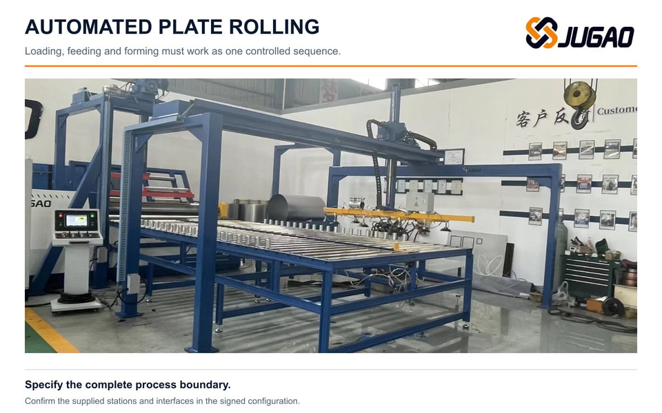
At each station boundary, name the sending device, receiving device and signal that permits transfer. Define what happens when the receiver is occupied, a sensor disagrees or a cycle stops halfway through. The station map below is a proposed specification structure; the signed quotation should identify the modules actually supplied. Welding, automatic gauging and upstream cutting need their own scope, fixtures and interface definitions when required. Assign responsibility for every boundary so an upstream machine cannot release material into an unready downstream station.
| Station | Input → output | Interface to agree |
|---|---|---|
| 01 · Intake | Plate stack → one identified sheet | Separation, double-sheet detection, stack limits |
| 02 · Align | Released sheet → defined entry datum | Skew limit, guide position, roll-entry permission |
| 03 · Form | Approved blank and recipe → rolled shell | Pre-bending, roll positions, support sequence |
| 04 · Unload | Supported shell → receiving station | End opening, receiver position, full travel clearance |
| 05 · Inspect | Measured shell → accepted part or hold | Diameter, seam condition, quality record, traceability |
Release one sheet and verify the grip
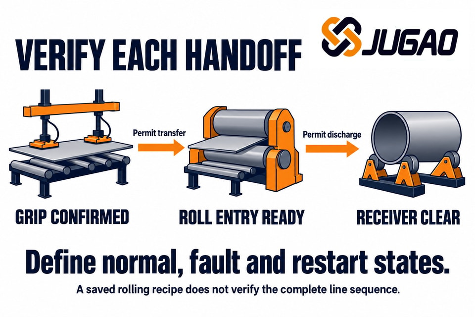
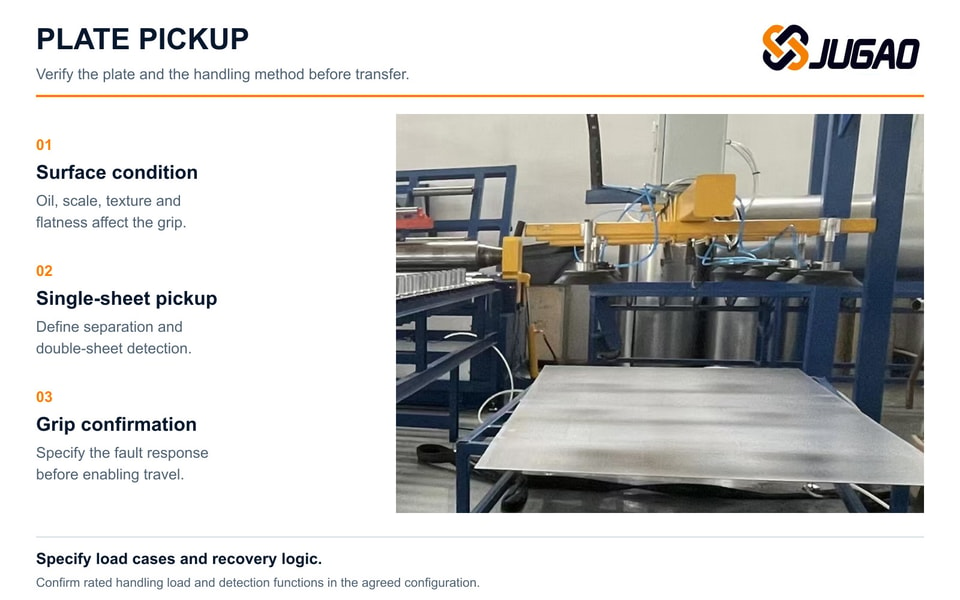
The plate pickup arrangement brings sheet separation, surface condition and grip confirmation into the loading sequence. Record the permitted blank envelope, surface oil or scale, flatness, stack height and maximum workpiece mass. Ask JUGAO to identify the configured gripping method and its working limits, then demonstrate the agreed response to an unsuccessful pickup or a detected double sheet. Define a controlled recovery position and who may restart. A nominal sheet thickness alone does not establish whether the loading system can handle the production mix.
- Before travel: one-sheet confirmation and an accepted grip state.
- Before release: receiver ready and plate support established.
- After an interrupted move: reconciled station state and authorized restart.
Align the reference edge before forming
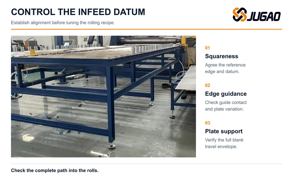
The roller table and side guides establish the approach to the rolls. Agree which blank edge is the datum, how squareness is checked and which skew or positioning condition blocks entry. Blank length in the direction of rolling and cylinder axial width must be specified separately. Include edge burrs, camber and flatness in the incoming-material limits. Verify the entire travel of the largest blank, including its overhang and support at the handoff; checking the empty conveyor leaves these workpiece-dependent conditions unresolved.
Define the recipe and the operating states
Approve the recipe and control revisions
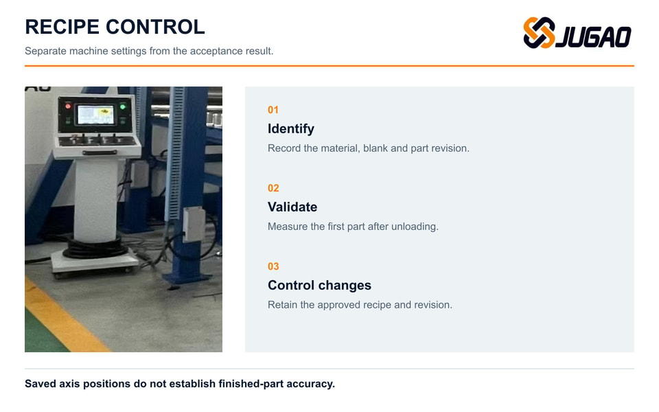
A saved rolling recipe is one part of a coordinated line. Define the material identification, blank revision, process settings and approved measurement record that belong to each recipe. After setup or a material change, validate the first piece after unloading before releasing the production batch. Record who may edit the recipe, how revisions are identified and which change triggers a new approval. In the RFQ, list the operator tasks that remain during normal production, changeover and recovery; an integrated line can still require planned human intervention.
| Automation layer | Scope to confirm |
|---|---|
| Manual setup | Operator positioning, adjustment and observation |
| CNC forming | Approved recipe, axis sequence and first-piece checks |
| Automatic handling | Sheet separation, pickup, alignment and supported unloading |
| Integrated production line | Coordinated stations, buffers, inspection, operator intervention and fault recovery |
Describe the material and the finished shell
Build a workpiece matrix
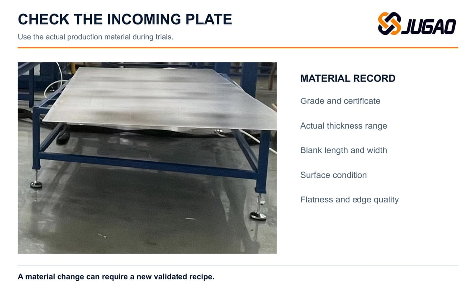
Send a matrix of the intended part families, including the most demanding combinations rather than only separate maximum dimensions. A wide, strong plate at the smallest target diameter may govern forming; a long, thin sheet may govern handling and support. Specify the range of thickness and strength that production will actually use, and choose representative trial blanks from that range. Keep material identification with the part record so a recipe adjustment can be traced to a particular grade, lot or incoming condition.
| Input family | Buyer information | Acceptance definition |
|---|---|---|
| Material | Grade, certificate or measured strength, heat/lot, thickness range, surface and flatness | Material identity and approved recipe revision |
| Geometry | Rolling-direction length, axial width, target ID or OD, thickness tolerance | Measurement sections, stage, seam and support condition |
| Quality | Roundness/ovality, residual straight ends, seam gap, end-face condition, surface marks | Drawing limits, instruments and agreed measurement method |
| Production | Accepted parts per shift, family mix, changeovers, inspection and downstream waits | Counting boundary, test duration and intervention rules |
| Installation | Utilities, floor/foundation, headroom, travel, access and guarding | Approved layout and installed-site verification |
Define the diameter and its measurement condition
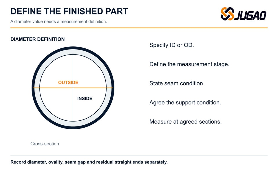
State whether the drawing calls for inside diameter (ID) or outside diameter (OD), the permitted deviation and the stage of measurement. An open rolled shell, a supported shell and a welded cylinder can have different measured geometry. Agree the axial sections, angular positions, seam gap and support condition used during inspection. Define roundness or ovality explicitly instead of treating the two terms as interchangeable. Record the residual straight length at each end separately from the diameter result; one diameter reading cannot establish every required quality characteristic.
Check both ends against pre-bending capacity
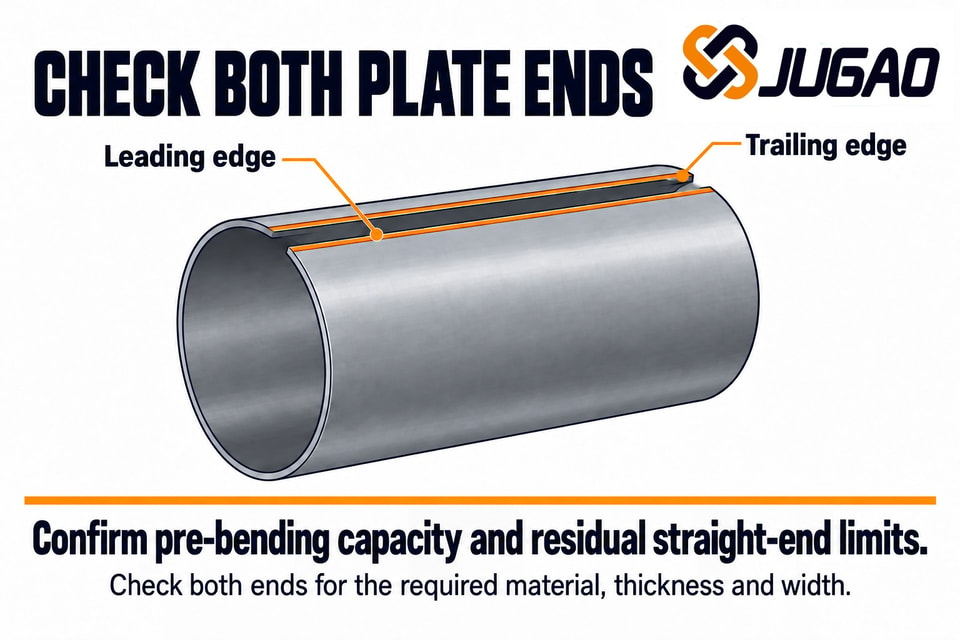
Ask for a capability matrix that distinguishes main rolling from leading-end and trailing-end pre-bending at the required material strength, thickness, width and finished diameter. Include the allowable residual straight length at each end, the planned pass sequence and any repositioning or manual intervention. Make these conditions part of the sample trial. A headline maximum rolling thickness leaves the seam-adjacent geometry unresolved, especially when the finished shell must enter a tight welding fixture or meet a defined seam-opening limit.
Revalidate the recipe when material changes
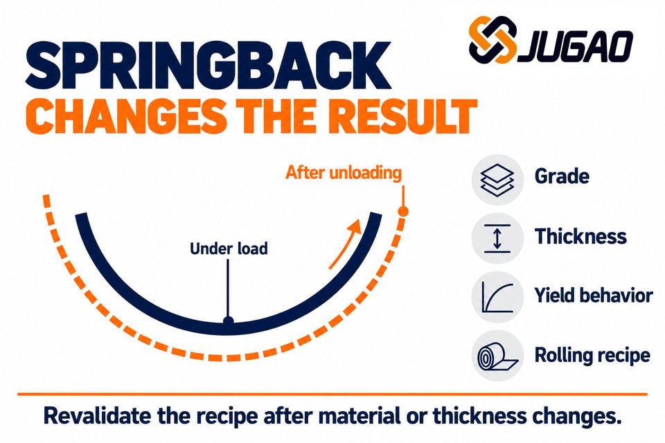
Elastic recovery after unloading changes the final curvature. Outokumpu’s guidance on bending and roll bending explains that steel grade and sheet-thickness changes can require machine adjustment because springback varies. For the production plan, retain the actual material and thickness alongside the approved recipe, then repeat the agreed first-piece checks after a relevant change. If a trial misses diameter or seam requirements, record the adjustment and measured result before locking the new revision. Treat recipe reuse as a controlled process supported by measurement.
Confirm the forming capacity as a complete set
Select the forming station within the complete line
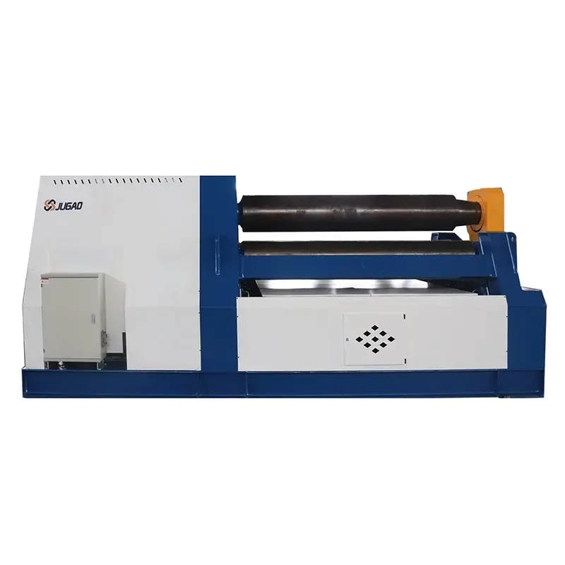
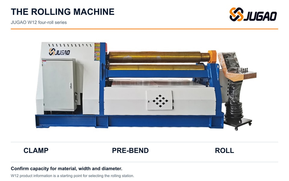
Use the JUGAO W12 four-roll product page to discuss the rolling station and its connection to the handling equipment. Request a written selection for your material and finished geometry, together with the required support, opening and unloading arrangement. The quotation should separate the machine, handling modules, control integration and acceptance services. Confirm responsibility for mechanical clearances and interlocks across the supplied scope, and identify any buyer-supplied equipment that must be present or simulated during the factory trial.
Resolve the published capacity conditions
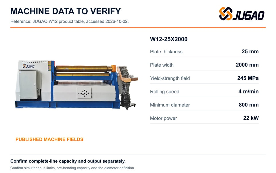
The W12-25X2000 table row provides the fields below. Request confirmation that the selected operating conditions apply together. The page’s general diameter wording refers to 1.1 times the upper-roll diameter, while 800 ÷ 350 is approximately 2.29; the applicable definitions need clarification. Its ±0.2 mm synchronization claim also needs a measurement definition and cannot be used as a finished-roundness tolerance. Keep the requested capacity, quality and total-line utility ratings explicit in the signed technical agreement.
| W12-25X2000 published field | Value | Confirmation needed for the selected part |
|---|---|---|
| Maximum rolling thickness / width | 25 mm / 2,000 mm | Combined material, width, diameter and pre-bending conditions |
| Yield-strength column | 245 MPa | Applicable material rating and actual production strength |
| Rolling speed | 4 m/min | Travel speed versus complete accepted-part cycle |
| Minimum diameter / upper-roll diameter | 800 mm / 350 mm | ID/OD convention, measurement stage and applicable configuration |
| Motor power | 22 kW | Separate the listed motor from total line connected load |
Calculate the load and model the cycle
Example A · calculate the sheet mass
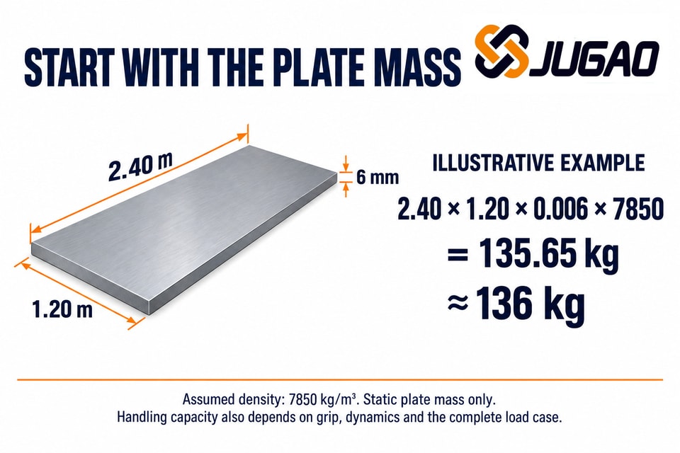
For an illustrative carbon-steel blank 2.40 m long, 1.20 m wide and 6 mm thick, assume a density of 7,850 kg/m³. Multiplying volume by density gives about 136 kg of static bare-sheet mass. Selection must use the heaviest permitted production blank, including positive dimensional tolerances. Keep the gripping device’s workpiece rating distinct from the gantry’s total suspended-load rating. Tool mass, acceleration, eccentric loading and the specified safety factors must be checked against the correct component rating by the equipment supplier.
= 135.648 kg ≈ 136 kgDimensions in m · assumed carbon-steel density in kg/m³
- Gripping device: check the permitted workpiece working load and contact conditions.
- Gantry or lifting axis: check the total suspended load, including the gripping tool, against its rating.
- Complete assembly: verify allowable motion, eccentricity, sheet stiffness and loss-of-grip protection under the manufacturer’s design criteria.
Example B · model the shared resources
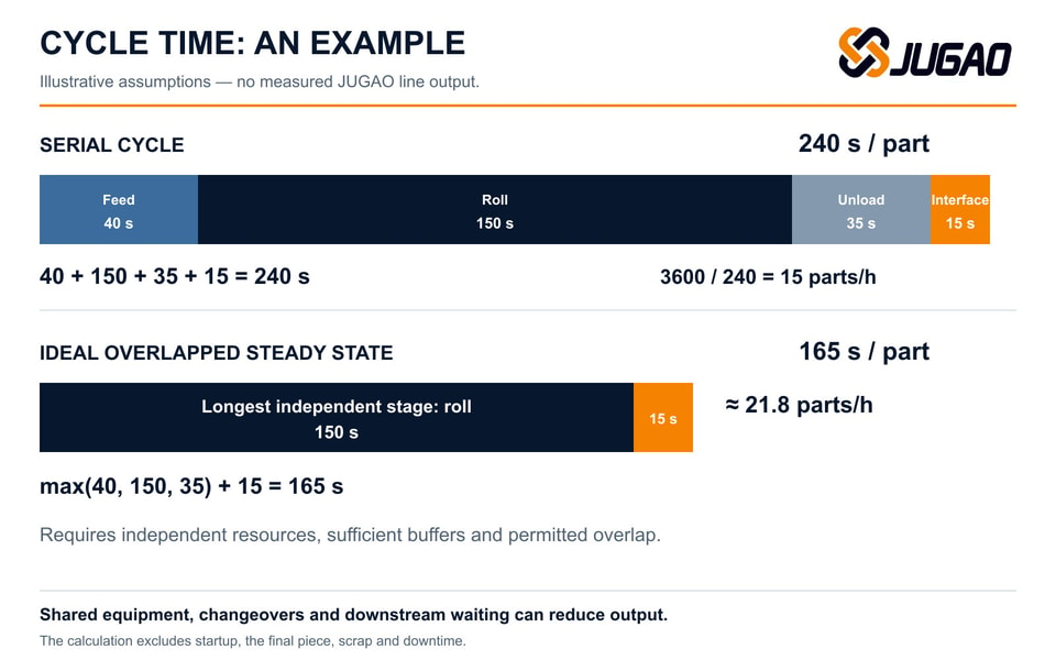
Assume feed takes 40 s, rolling and pre-bending 150 s, unloading 35 s and a non-overlapped interface 15 s. Serial operation totals 240 s per part. The 165 s alternative assumes independent resources, adequate buffers and permitted overlap in steady state; startup, the final part, changeovers, scrap and downtime are excluded. A shared gantry or an occupied receiver can invalidate that model. These figures are illustrative calculations. Establish contractual output from measured accepted parts over an agreed run, recording waits and interventions as well as station motion.
| Model | Assumed calculation | Ideal output |
|---|---|---|
| Serial cycle | F + R + U + J = 40 + 150 + 35 + 15 = 240 s/part | 3,600 ÷ 240 = 15 parts/h |
| Overlapped steady state | max(F, R, U) + J = 150 + 15 = 165 s/part | 3,600 ÷ 165 ≈ 21.8 parts/h |
Plan the receiving station and the site
Support the shell through the complete discharge movement
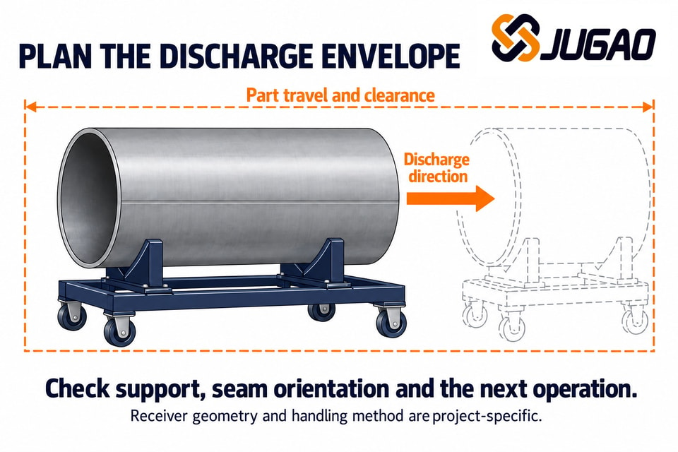
Specify shell mass, axial length, diameter range, seam orientation and the receiving support geometry. The release sequence should establish support before the machine opens or transfers the part, with receiver readiness and clearance confirmed at the appropriate steps. Review the complete motion envelope, including the shell’s extremities and the receiver’s travel. If the next operation is welding, agree who supplies the fixture, how the shell is located and which dimensional or seam condition permits the handoff. Record the recovery method for a stopped or incomplete transfer.
Verify the installed layout and utilities
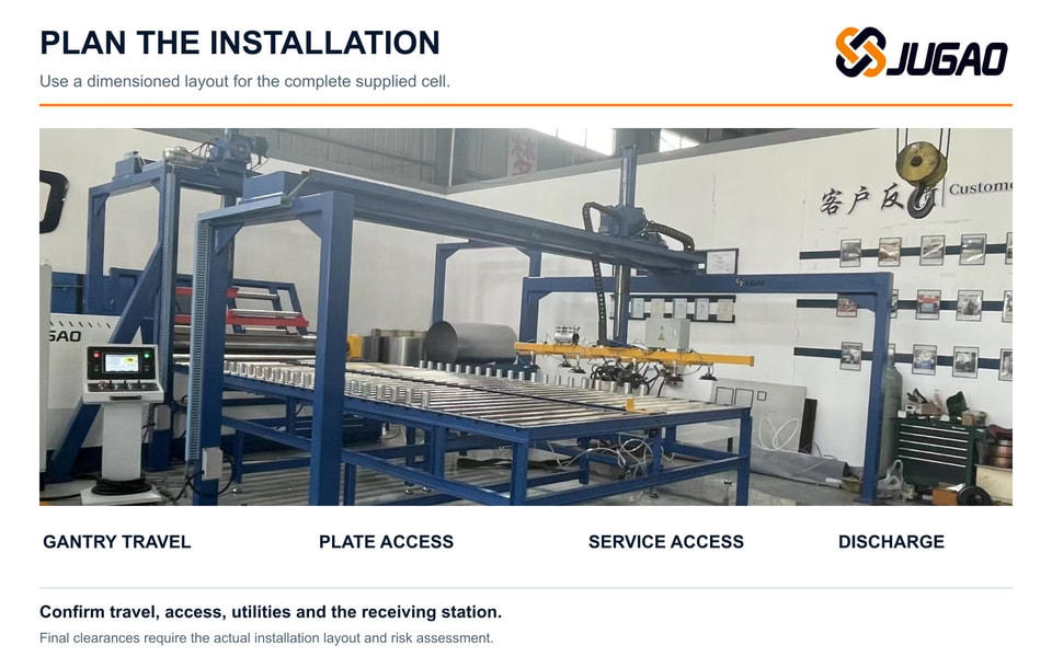
Create a dimensioned plan covering stack replenishment, gantry travel, maximum blank overhang, shell discharge, operator routes and maintenance access. Check headroom, foundation and floor requirements against the actual equipment loads and the supplier’s installation information. List electrical, pneumatic and hydraulic requirements for the complete supplied configuration, including auxiliary equipment. During SAT, repeat the agreed interface checks with the buyer’s actual material flow and utilities. Any layout or downstream change made after FAT needs review before the same acceptance result can be carried forward.
Verify the complete cell’s protective functions
Define protective functions and controlled fault tests
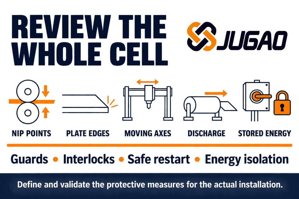
Review hazards across the complete installation: roll nips, moving plates, suspended loads, supports, traveling axes and stored energy. OSHA 1910.212 addresses machine guarding; OSHA 1910.147 addresses hazardous-energy control during covered servicing. Use the references below to agree the applicable design and verification basis with qualified personnel. Perform fault simulations only under an approved test plan with protected test conditions; document the expected safe state, observed response and restart authority. Referencing a standard alone does not establish conformity of a supplied line.
- Sheet or grip fault: double-sheet signal, plate skew or low holding capacity.
- Transfer fault: receiver occupied, support absent or station communication lost.
- Protective functions: guard/interlock response, emergency stop, reset and prevention of unexpected restart.
- Service state: isolation points, stored energy and the verified maintenance procedure.
| Review area | Reference | Evidence to request |
|---|---|---|
| U.S. machine guarding | OSHA 1910.212 | Guarding review for operating points, nip points and rotating parts |
| U.S. hazardous-energy control | OSHA 1910.147 | Machine-specific isolation, stored-energy control and servicing procedures |
| Risk assessment and reduction | ISO 12100:2010 | Applicability, design basis and documented verification |
| Fixed and movable guards | ISO 14120:2015 | Applicability, design basis and documented verification |
| Reach-related safety distances | ISO 13857:2019 | Applicability, design basis and documented verification |
| Guard interlocks and selection | ISO 14119:2024 | Applicability, design basis and documented verification |
| Safety-related control-system design | ISO 13849-1:2023 | Applicability, design basis and documented verification |
| Emergency-stop function | ISO 13850:2015 | Applicability, design basis and documented verification |
Build an RFQ that can be verified
Turn the production requirement into a signed scope
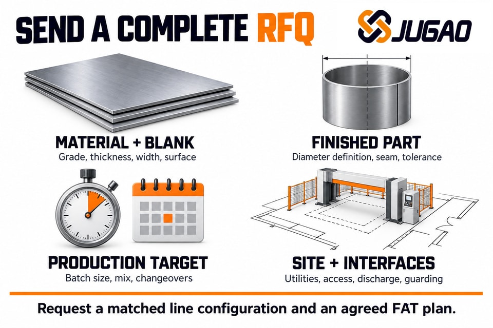
Send JUGAO the workpiece matrix and installation constraints, then request a matching capability matrix, total layout, station list, module bill of materials and interface responsibilities. The reply should include rated handling conditions, utilities, safety functions, operator tasks, training, spares and an agreed FAT/SAT plan. Resolve open fields before committing to the production target. A useful technical agreement connects each critical workpiece requirement to a supplied module and a verification record, making later design changes and acceptance decisions easier to trace.
- Workpiece matrix: material, actual strength range, thickness, blank dimensions, maximum mass, target geometry and drawing tolerances.
- Handling envelope: gripping conditions, stack limits, tool load, motion path, support and receiving equipment.
- Control scope: recipe management, operating modes, permissions, station interfaces, fault response and recovery.
- Production requirement: accepted output, family mix, changeover, staffing assumptions and counting boundary.
- Site information: installation plan, utilities, floor/foundation, headroom, access and downstream integration.
- Acceptance plan: samples, run duration, measuring methods, intervention rules, limits and required records.
Follow the part with an acceptance record
Use the same acceptance definitions at FAT and SAT
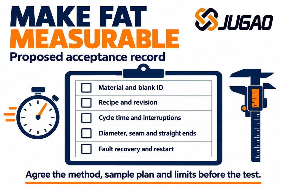
Factory acceptance testing (FAT) uses agreed samples and defined or simulated interfaces at the supplier’s site. Site acceptance testing (SAT) checks the installed line with actual utilities and upstream/downstream conditions. As a planning example, propose at least ten continuous cycles per agreed representative condition, then set the final sample size and run duration by contract. Record cycle mean, median, maximum, interruptions and accepted output, alongside dimensional results. Retain raw time stamps and change records; a single best cycle is insufficient evidence for sustained production.
| Record | Blank entry | Acceptance basis |
|---|---|---|
| Material and setup | Grade/lot ___ · actual thickness ___ · blank revision ___ · recipe ___ | Matches the agreed sample matrix |
| Continuous run | Target cycles ___ · observed ___ · accepted parts ___ · interventions ___ | Run duration and intervention rules agreed before test |
| Station timing | Pick ___ · roll ___ · unload ___ · interface/wait ___ | Time stamps and event definitions retained |
| Part geometry | ID/OD ___ · sections ___ · support ___ · seam gap ___ · straight ends ___ | Drawing limits and agreed measurement method |
| Controlled fault tests | Test ID ___ · expected state ___ · observed state ___ · recovery ___ | Approved protected test plan and recorded result |
| Installed-site check | Utilities ___ · layout ___ · downstream ___ · changes ___ · SAT sign-off ___ | Buyer-site conditions verified against the agreement |
Frequently asked questions
Is a CNC four-roll machine already an automatic line?
CNC forming covers the programmed rolling sequence. Specify loading, sheet separation, alignment, supported unloading, inspection and station recovery separately. Use the automation scope table above to identify which functions are included and where operator intervention remains.
Can rolling speed be converted directly into parts per hour?
Rolling speed describes one motion. Whole-line output depends on feed, forming passes, support, unloading, inspection, shared resources and waiting. Measure accepted parts over the agreed run and retain the station timing; the cycle example above shows the assumptions needed for an overlap calculation.
What should I send with a quotation request?
Send the workpiece family, material and strength range, thickness tolerances, rolling-direction length, axial width, maximum mass, target ID or OD and quality limits. Add the required accepted output, family mix, site plan, utilities and downstream interfaces. Attach representative part drawings.
Can an existing recipe be reused after a material change?
Revalidate the first piece when the agreed change criteria are met. Grade and thickness affect springback, as explained in Outokumpu’s forming guidance. Keep the material record, recipe revision and measured unloaded geometry together before releasing the batch.
How should the loading device be selected?
Specify the heaviest permitted blank, surface condition, stiffness, pickup geometry and travel. Check the gripping device’s workpiece limit and the lifting axis’s total suspended-load limit separately. Require supplier confirmation of holding conditions, double-sheet detection and the response to loss of holding capability.
Does automatic rolling include welding?
Include welding only when the technical agreement names the welding station, fixture, handoff, inspection and acceptance responsibility. Define seam gap, shell support and orientation at transfer. These requirements also determine whether the receiving station can release the rolling machine for the next cycle.
What should the acceptance record prove?
The record should demonstrate the agreed material and part conditions, continuous-run behavior, geometry, interventions and protective-function tests. Preserve the test method and raw results. SAT then checks the installed interfaces and records changes from the factory-tested configuration.
Which safety documents should the buyer request?
Request the risk assessment, guarding and access review, safety-function specification, control-system verification, controlled test records and energy-isolation procedure. Agree applicable regulations and standards for the installation. Keep responsibilities for the complete integrated cell clear between the equipment suppliers and site operator.
Sources and further reading
- JUGAO W12 four-roll seriesProduct reference and published single-machine fields
- Outokumpu · Forming of stainless steelGrade, thickness and springback in roll bending
- OSHA 29 CFR 1910.212General machine-guarding requirements
- OSHA 29 CFR 1910.147Control of hazardous energy during covered servicing
- ISO 12100:2010Risk assessment and reduction
- ISO 14120:2015Fixed and movable guards
- ISO 13857:2019Reach-related safety distances
- ISO 14119:2024Guard interlocks and selection
- ISO 13849-1:2023Safety-related control-system design
- ISO 13850:2015Emergency-stop function
Contact Us