 Get a quote
Resources
4 Common Methods for Inspecting Weld Quality
Weld quality directly determines the strength, safety, and service life of a workpiece. Substandard welds can lead to fractures, leaks, or the total loss of a component, and may even create serious safety hazards. Many companies, lacking standardized inspection procedures, inadvertently allow defective products to reach the market—a mistake that not only drives up rework costs but also damages brand reputation. In reality, assessing weld quality does not necessarily require complex equipment. By mastering four common techniques—visual inspection, penetrant testing, ultrasonic testing, and destructive testing—you can cover the entire spectrum of quality assurance, from initial screening to precise verification. This article breaks down the key operational steps and ideal use cases for each method, making them immediately applicable whether you are a novice inspector or looking to formalize processes in an established manufacturing facility.
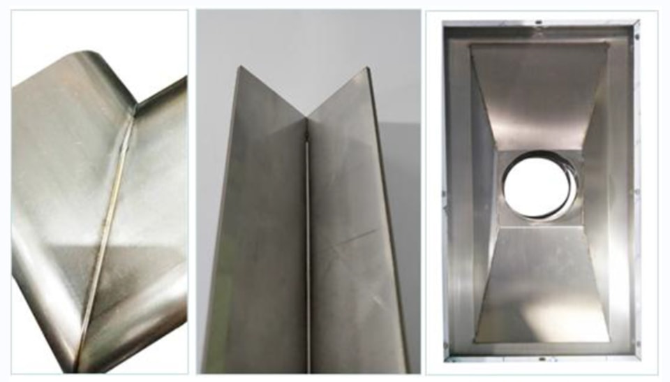
Core Principle: Weld quality inspection should follow a logical progression—moving from the simple to the complex, and from the surface to the interior. Start by using straightforward methods to identify obvious surface defects, then employ specialized techniques to uncover hidden internal issues, and finally, use sampling to verify overall compliance. This approach optimizes both cost and efficiency.
1. Method 1: Visual Inspection (The most fundamental and accessible approach; suitable for all personnel)
Visual inspection serves as the first line of defense in weld quality control. It is the most basic and convenient method, requiring no specialized equipment or advanced technical skills. By using the naked eye—or perhaps simple hand tools—inspectors can quickly identify over 80% of visible surface defects. It is the ideal initial screening tool for any welded workpiece and serves as the standard "first-pass" quality check in high-volume manufacturing environments. 1. Core Inspection Scope
Visual inspection focuses on three key areas—weld morphology, surface defects, and the overall condition of the workpiece—to accurately identify common surface issues:
First, weld dimensions: Verify that the height, width, and length of the weld meet design specifications. Ensure that the weld is neither too narrow nor too wide, that its profile is uniform, and that it meets the required length. Dimensional deviations should remain within an acceptable range (typically no more than ±1 mm).
Second, surface defects: Check for common issues such as cracks, porosity, undercut, lack of penetration, weld spatter/excess metal (weld beads), and slag inclusions. Cracks are the most critical defects, appearing as linear fissures distributed irregularly across the weld surface or at the joints. Porosity manifests as small, circular or elliptical voids, caused by gases trapped during the welding process. Undercut refers to grooves or depressions along the edges of the weld, often resulting from excessive welding current or improper torch/electrode angles. Excess weld metal (weld beads/lumps) consists of protruding material that can interfere with the assembly or final appearance of the workpiece.
Third, workpiece condition: Observe the workpiece for any visible deformation or warping following the welding process, and ensure that the joined components are properly aligned. This helps prevent welding-induced distortion from complicating subsequent machining or assembly steps.
2. Tools and Procedures (Practical and Easy to Implement)
Tools required: A straight edge (ruler), a weld gauge (optional), and a flashlight (to illuminate weld details and ensure no defects are overlooked due to poor lighting). No specialized, high-end inspection equipment is necessary. Operational Steps: Step 1: Pre-process the workpiece by removing rust, oil, and welding slag from the weld surface to ensure it is clean and clear for inspection. Step 2: Perform a visual inspection—under natural or bright artificial light, slowly scan along the length of the weld, paying particular attention to areas prone to defects, such as weld edges and joints; record the location and nature of any identified defects. Step 3: Measure dimensions—use a ruler to determine the weld length, and a weld gauge (or a ruler for estimation if a gauge is unavailable) to measure the weld height and width; compare these measurements against the design drawings to verify compliance. Step 4: Make a preliminary assessment—if significant issues such as obvious cracks, extensive porosity, or major dimensional deviations are found, the weld is immediately deemed non-compliant; no further testing is required, and the part must be sent for rework.
3. Pitfalls to Avoid
Ensure adequate lighting to prevent missing defects—use a flashlight to illuminate the area, especially when looking for fine cracks or tiny pores. When removing welding slag, work carefully to avoid damaging the weld surface, which could be mistaken for a defect. Do not overlook "micro-cracks"; even a tiny surface crack may extend deep into the material, necessitating further inspection or immediate rework.
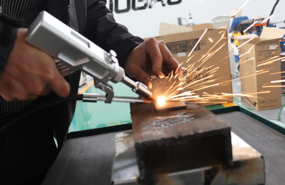
II. Method 2: Penetrant Testing (A convenient, non-destructive method for detecting surface and near-surface micro-defects)
Penetrant testing is a non-destructive testing (NDT) method that does not damage the workpiece. It is primarily used to detect surface and near-surface micro-defects (with a depth of ≤2 mm)—such as fine cracks, tiny pores, or crevices—that are difficult to see with the naked eye. This method is suitable for inspecting welds in most metallic materials, including stainless steel, carbon steel, and aluminum. It is particularly effective for workpieces with complex shapes or rough surfaces, serving as a valuable complement to visual inspection. 1. Core Inspection Principle (Simplified)
This method leverages the capillary action of liquids. A penetrant is applied to the surface of a weld, allowing it to seep into minute surface defects—such as tiny cracks or crevices. After removing any excess penetrant from the surface, a developer is applied. The developer draws the penetrant out from within the defects, making them clearly visible. This enables the identification of the location, shape, and size of the defects, facilitating the rapid detection of hidden flaws on or near the surface.
2. Tools and Operational Steps
Required Tools: Penetrant, cleaner, and developer (used as a set), along with absorbent cotton, sandpaper, and a hairdryer (optional, for rapid drying of the workpiece). These materials are cost-effective and can be purchased in bulk for factory use. Operational Steps: Step 1: Surface Pretreatment –This is a critical step. Use sandpaper to abrade the weld seam and the surrounding 20mm area to remove rust, oil, oxide scale, and weld spatter. Ensure the surface is free of oil and loose debris, and sand the weld surface until smooth (avoid excessive roughness, which could trap the penetrant and lead to false-positive results). Afterward, wipe the surface clean with absorbent cotton and allow it to dry completely. Step 2: Application of Penetrant – Apply the penetrant evenly—either by spraying or brushing—across the weld seam and the surrounding area, ensuring full coverage. Keep the workpiece level to allow the penetrant to seep thoroughly into any minute defects. The typical dwell time at room temperature is 10–20 minutes (this may be extended if the temperature is low). Step 3: Removal of Excess Penetrant – Using absorbent cotton dampened with a cleaner, gently wipe the surface perpendicular to the weld seam until no visible excess penetrant remains. Exercise caution to avoid wiping the penetrant out of the defects themselves, which could result in missed detections. Step 4: Application of Developer – Shake the developer well, then spray it evenly onto the weld seam from a distance of 15–30cm to create a thin, uniform film. Avoid applying the developer too thickly, as this can obscure the appearance of defects. Allow it to sit for 5–10 minutes so the developer can effectively draw out the penetrant trapped within any defects. Step 5: Observation and Evaluation – Examine the developer film under natural light. The appearance of distinct colored lines (matching the color of the penetrant) or spots indicates the presence of defects. The type of defect can be identified by the shape of the indication (e.g., linear patterns suggest cracks, while dot-like patterns suggest porosity).
3. Applicable Scenarios and Limitations
Applicable Scenarios: This method is primarily used to detect open surface or near-surface defects in welds, such as fine cracks, micro-porosity, and slag inclusions. It is particularly well-suited for workpieces with complex geometries or rough surfaces (e.g., irregularly shaped hardware components or pipe fittings), as well as for identifying latent surface defects that cannot be detected through visual inspection alone. Limitations: It cannot detect deep-seated internal defects; it is limited to the surface and near-surface regions (depth ≤ 2 mm). It is highly sensitive to surface roughness—if the surface is too rough, the penetrant may become trapped, potentially leading to false-positive indications; therefore, proper surface preparation is required. It is also unsuitable for testing porous materials (such as cast iron).
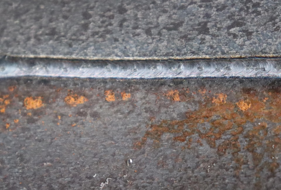
III. Method 3: Ultrasonic Testing (For internal defects; a core non-destructive testing method)
Ultrasonic testing (UT) is the primary method used in industrial welding to detect internal defects. As a non-destructive testing (NDT) technique, it does not damage the workpiece. It can precisely locate internal defects and determine their depth and size. It is suitable for welds with significant thickness (≥ 8 mm)—such as those found in steel structures, pressure vessels, pipelines, and thick steel plate welds—and is a mandatory inspection step for critical components (load-bearing or pressure-retaining parts) to effectively identify hidden internal flaws.
1. Core Principle
High-frequency sound waves, emitted by an ultrasonic transducer (probe), penetrate the weld and enter the workpiece. Within a homogeneous material, these sound waves travel in a straight line. When the waves encounter an internal defect (such as a crack, lack of penetration, or slag inclusion), they are reflected. The transducer receives these reflected signals, and an ultrasonic flaw detector displays the resulting waveforms on a screen. By analyzing the position and amplitude (height) of these waveforms, inspectors can determine the location (depth and width), size, and type of the internal defect, allowing for the precise identification of hidden flaws.
2. Tools and Procedure (Requires basic training)
Equipment preparation: Ultrasonic flaw detector; transducers (selected based on workpiece thickness—typically straight-beam probes for thinner sections and angle-beam probes for thicker sections); couplant (such as machine oil or a specialized coupling agent, used to facilitate sound wave transmission and minimize signal loss); and sandpaper (for surface preparation). Operational Procedure: Step 1: Pre-treatment of the workpiece—remove rust, oil, and welding slag from the weld seam and surrounding surfaces to ensure a smooth, clean finish, thereby preventing poor contact between the probe and the workpiece surface, which could compromise inspection accuracy. Step 2: Instrument calibration—calibrate the ultrasonic testing (UT) instrument using a standard reference block (containing known defects); adjust parameters such as probe angle and sensitivity to ensure inspection accuracy and avoid missed detections or false positives caused by improper settings. Step 3: Application of couplant—apply a small, even layer of couplant to the base of the probe and the surface of the weld seam to ensure optimal contact between the probe and the workpiece, eliminating any air gaps. Step 4: Scanning—move the probe slowly along the length of the weld seam, maintaining a perpendicular or specific angle (adjusting the angle as necessary when using an angled probe). Move the probe at a constant speed while monitoring the waveform signals displayed on the instrument screen. Step 5: Defect evaluation—if an abnormal reflection (a signal exceeding the reference threshold) appears on the screen, record its position and amplitude. Based on these data and professional experience, determine the type of defect (e.g., cracks typically produce sharp, continuous reflections, while slag inclusions result in broader, discontinuous signals) and estimate the depth and size of the defect.
3. Applicable Scenarios and Advantages
Applicable Scenarios: Primarily used for detecting internal defects in weld seams with a thickness of ≥8mm. It is widely employed in the inspection of critical components—such as those found in steel structures, pressure vessels, pipelines, automotive parts, and heavy machinery—and is particularly well-suited for load-bearing or pressure-retaining components, ensuring the absence of hidden internal flaws.
Core Advantages: Non-destructive testing (NDT) that leaves the workpiece intact and allows for repeated inspections; deep penetration capability, enabling the detection of internal defects in components several meters thick; high speed and efficiency, making it ideal for batch inspections; cost-effectiveness, as equipment is reusable and requires minimal maintenance; and the ability to precisely locate and size defects, facilitating subsequent rework or repairs.
IV. Method 4: Destructive Testing (Sampling-based verification for determining ultimate performance)
Destructive testing is a form of "sampling-based verification." It involves taking samples from workpieces and subjecting them to mechanical testing. By destroying the samples, one can evaluate mechanical properties—such as weld strength and toughness—to determine whether the welding quality meets design specifications. Although this method results in the destruction of the samples, it provides the most direct and accurate assessment of a weld's ultimate performance. It is typically used for sampling during mass production or for process validation during the trial welding of new products, ensuring that the weld strength of the manufactured parts meets the required standards.
1. Common Test Types and Procedures (The two most frequently used methods)
(1) Tensile Testing (Used to evaluate weld strength; the most critical test)
Test Principle: A welded specimen is secured in a tensile testing machine and subjected to an axial tensile force until it fractures. The maximum force at the point of fracture is used to determine the tensile strength of the weld. This ensures that the weld strength is at least equal to that of the base material, preventing weld failure during service.
Operational Steps: Step 1: Specimen Preparation—Extract a welded specimen in accordance with industry standards. The dimensions of the specimen are determined by the material thickness; typically, it is rectangular, with the weld positioned in the center to ensure the tensile force is applied uniformly across the weld. Step 2: Specimen Mounting—Secure the specimen into the grips of the tensile testing machine, adjusting them to ensure the load is applied evenly without any misalignment. Step 3: Applying Tensile Force—Activate the tensile testing machine to apply an axial tensile force at a constant, controlled speed. Observe the deformation of the specimen and record the maximum force at the moment of fracture. Step 4: Compliance Assessment—The weld is considered acceptable if its tensile strength is at least 90% of the base material's tensile strength, and if the fracture does not occur within the weld (or, if it does occur within the weld, the strength requirements are still met). (2) Bend Test (Evaluating Weld Ductility and Integrity)
Test Principle: A welded specimen is bent around a mandrel of a specified radius to a predetermined angle (typically 180° or 90°). The surface of the weld is then inspected for cracks or fractures. This assesses the weld’s ductility and integrity, ensuring it does not crack under stress or deformation due to insufficient ductility.
Procedure: Step 1: Specimen Preparation – Cut a rectangular specimen (typically 30 mm wide, with the length determined by the mandrel diameter), ensuring the weld is positioned on the outer (tension) side of the bend. Step 2: Positioning – Place the specimen on the mandrel of the bend-testing machine, ensuring the weld is on the outer side and that the load will be applied uniformly. Step 3: Application of Force – Activate the testing machine and apply pressure gradually to bend the specimen to the required angle (usually 180°). Maintain a steady speed to prevent excessive force from causing sudden fracture. Step 4: Inspection – Examine the weld surface after bending. The specimen is considered acceptable if there are no cracks or significant fractures (minor deformation is permissible).
2. Applications and Precautions
Applications: Used for sampling during mass production (typically 3–5 specimens per batch) to ensure weld strength meets standards; for process validation during the trial welding of new products to optimize welding parameters; and for specialized testing of critical components (such as load-bearing or pressure-retaining parts) to enhance product safety.
Precautions: Since this test is destructive, it cannot be performed on every finished component; therefore, it must be conducted via sampling. Results should be evaluated in conjunction with non-destructive testing (such as ultrasonic or penetrant testing). Ensure that specimen dimensions strictly adhere to relevant standards, as incorrect sizing can compromise test results. Additionally, testing equipment must be calibrated periodically to ensure measurement accuracy.
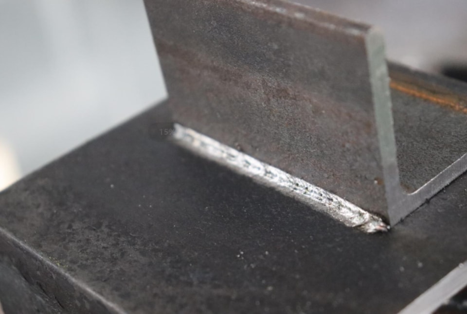
V. Summary of the Welding Quality Inspection Process (Ready for Factory Implementation)
By integrating the four inspection methods mentioned above and following a logical progression—from the superficial to the in-depth, and from the exterior to the interior—a universal welding quality inspection process has been developed. This process can be applied directly to both mass production and custom, single-unit manufacturing to ensure that welding quality consistently meets all requirements:
Step 1: Initial Inspection (Visual Inspection): Once welding is complete, operators or quality inspectors must conduct a 100% visual inspection. This involves cleaning the weld surfaces and identifying any visible defects (such as cracks, porosity, or dimensional inaccuracies). Non-conforming items must be sent for rework immediately and cannot proceed to subsequent production stages.
Step 2: Targeted Re-inspection (Penetrant/Ultrasonic Testing): For components that pass the visual inspection, critical parts—such as load-bearing, pressure-bearing, or visible aesthetic components—must undergo penetrant testing (for surface and near-surface defects) or ultrasonic testing (for internal defects). This step uncovers hidden flaws; any items that fail must be reworked and subsequently re-inspected.
Step 3: Sampling Verification (Destructive Testing): In mass production, 3–5 samples should be selected from each batch for tensile and bending tests to verify the strength and plasticity of the welds. If a sample fails, the sampling scope must be expanded to assess the entire batch, with full-scale inspection implemented if necessary.
Step 4: Final Comprehensive Assessment: Based on the results from the previous three steps, and in accordance with design specifications and industry standards (e.g., GB 50205 for steel structures or GB 150 for pressure vessels), a final determination of conformity is made. Conforming products are then moved to storage or the next production stage, while non-conforming products are either reworked or scrapped.
Additional Note: Welding quality requirements vary by industry. Inspection methods and acceptance criteria should be adjusted to align with the specific standards relevant to your sector. For instance, the welding of medical devices or automotive components requires stricter standards, necessitating more frequent inspections and a broader range of test parameters. Conversely, for general hardware components, the inspection process can be streamlined, focusing primarily on visual inspection and sampling verification.
VI. Summary of Pitfalls to Avoid in Inspection
1. Do not overlook visual inspection; surface defects often serve as "signals" for internal flaws. Conducting a thorough initial inspection can significantly reduce the costs associated with subsequent testing.
2. The core of penetrant testing lies in surface preparation. If the surface is unclean or uneven, it can easily lead to false positives, compromising the accuracy of the inspection results.
3. For ultrasonic testing, proper instrument calibration is essential. Incorrect probe angle adjustment can easily result in missing internal defects.
4. When performing destructive testing, ensure that test specimens are extracted according to standard specifications; otherwise, incorrect specimen dimensions may lead to erroneous test results.
The essence of weld quality inspection is "prevention." By following standardized inspection procedures to identify surface and internal defects early on, you can minimize rework costs while ensuring both product safety and service life. Whether you are a newcomer to the field or an established manufacturer, mastering these four common inspection methods will enable you to effectively resolve challenges related to weld quality assessment.
Related
Keep
reading.
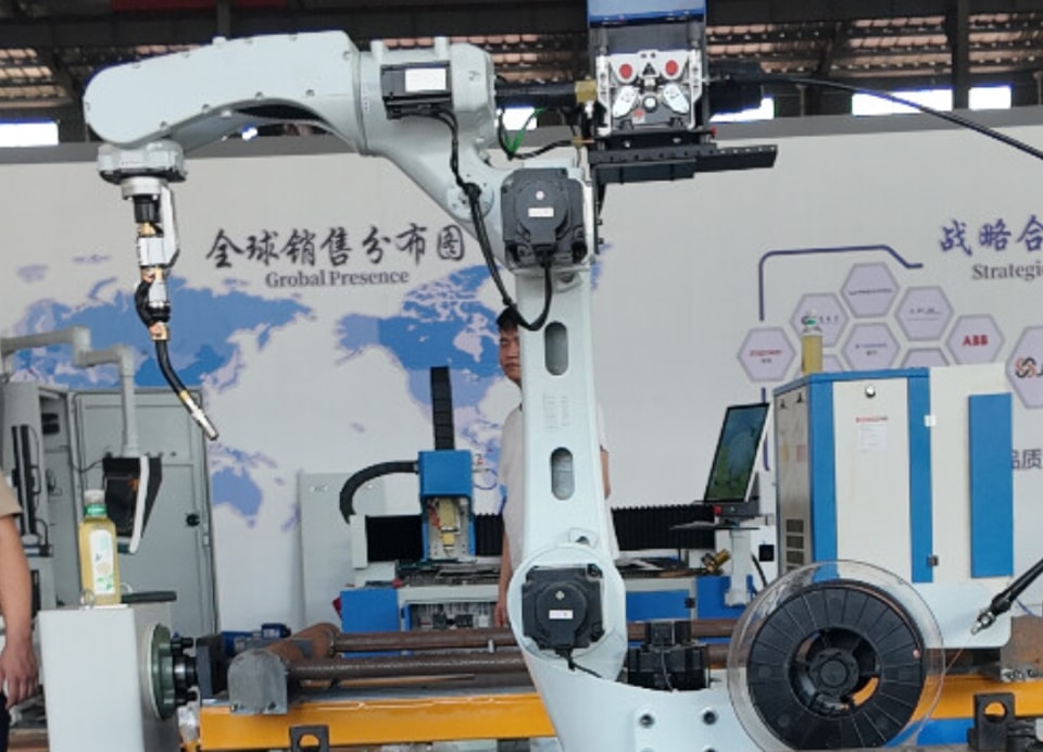 Comparison of Laser Welding Results and Application Scenarios Across Different Materials
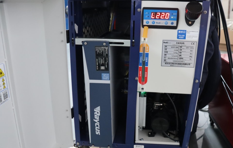 How to Choose Between Air-Cooled and Water-Cooled Laser Welding Systems
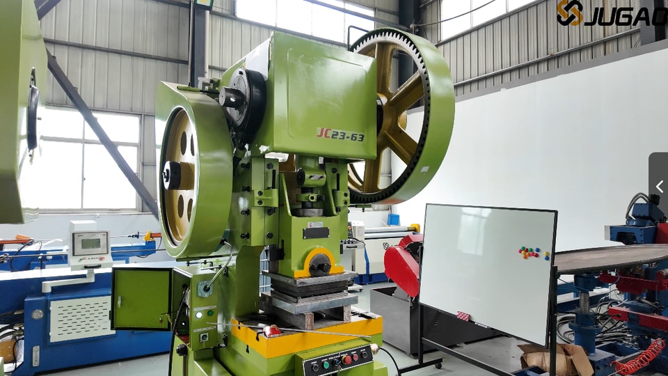 Understanding Punching Machines: Principles, Types, and Selection
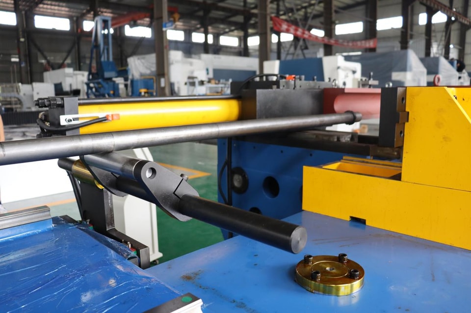 How can one effectively follow the installation guidelines for a pipe-bending machine?
 For which types of products is an automatic wire-feeding laser welding machine suitable?
 What Are the Latest Punching Machine Trends and Technological Breakthroughs?
 What Triggers Punching Machine Noise and How Can You Quieten It?
 What factors influence the replacement cycle of wear parts in a pipe-bending machine?
 Beyond price, what key parameters should you consider when purchasing welding equipment?
 Selecting the Top Punching Machines for Small Workshops & Heavy Industry
 How do you set the welding path for a robotic laser welding machine? Can it perform precise welding on complex workpieces?
 Essential Considerations Before Purchasing a Punching Machine
Engineering review
Send a drawing.
Get an engineer.
Standard selections answered within 4 hours. Parts outside the rules get a written process review within 24 hours.
- Part drawing: DXF, DWG, STEP or PDF
- Material and thickness
- Longest bend or cut length
- Yearly volume
Write to info@ntjugao.com or message the factory on WhatsApp +86 132 2211 1178.
Drawings (DXF, DWG, STEP, PDF): attach them to an email to info@ntjugao.com, quoting your name.