
Can a CNC Press Brake Bend Your Box? Check Bend Sequence, Tool Clearance and Part Removal
2026-10-03


Can your CNC press brake bend this box?
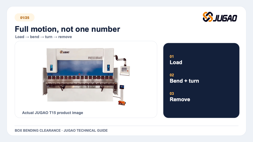
The answer is not one opening number. It is the complete motion from first load to final removal. A workable answer needs the released 3D part, actual installed tooling and the complete path of the workpiece. Screen every bend, reorientation and unloading movement before claiming that a catalogue dimension proves feasibility.
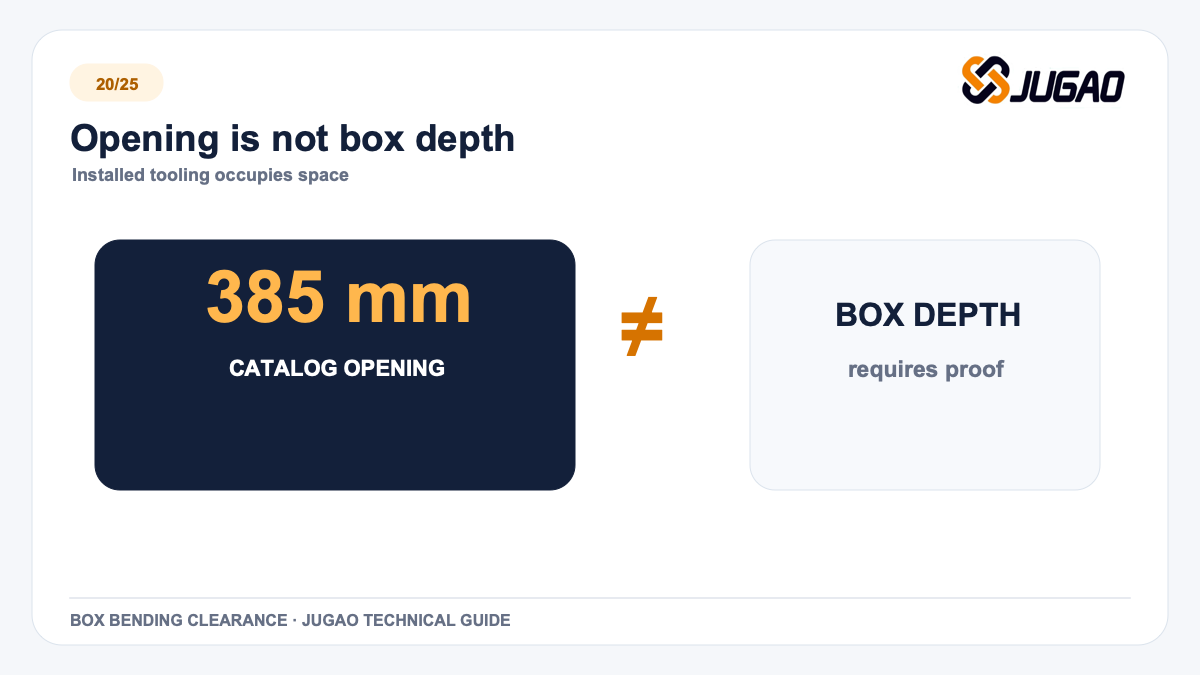
385 mm is a catalogue field.
Not a finished-box promise.
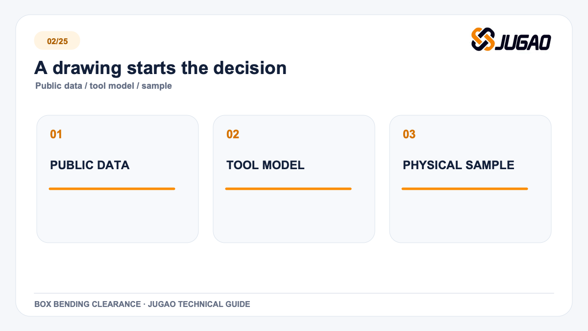
Use the public fields to start a screen. Use the drawing, installed-tool model and sample to close the decision. The machine page can filter obvious mismatches. The supplier must then review the exact drawing revision with the selected punch, die, clamps, holders and backgauge. Record unknowns explicitly; a missing tool profile is a request for data, not a pass.
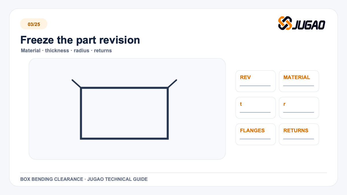
Read the drawing
Freeze revision, material, thickness, bend radii, flanges, returns, holes, reliefs and tolerances. Identify whether each value is an inside or outside dimension and show the bend-line datum. A finished outside dimension is not the flat blank size. Mark the open side, corner reliefs, return lips and surfaces that cannot be marked by tooling.
Model the motion
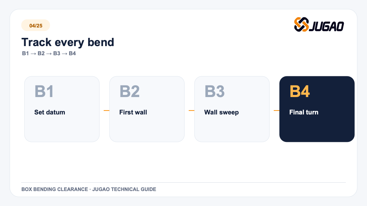
Check B1–B4, the backgauge datum, the formed-wall sweep and the support path. For each numbered bend, save the formed shape before and after the stroke. Show how the operator supports and turns the part, where the backgauge fingers touch, and how the final box leaves the tooling.
Prove the sample
Record dimensions, angles, surface condition, force and removal on representative material. Agree the acceptance drawing and measurement method before cutting material. Run a representative sample using the quoted tools and material, then record deviations and any required sequence change. Do not treat an unmeasured trial as approval.
Numbers help you screen.
They do not replace geometry.
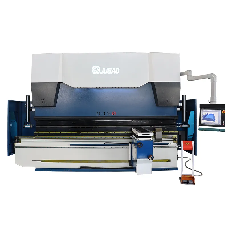
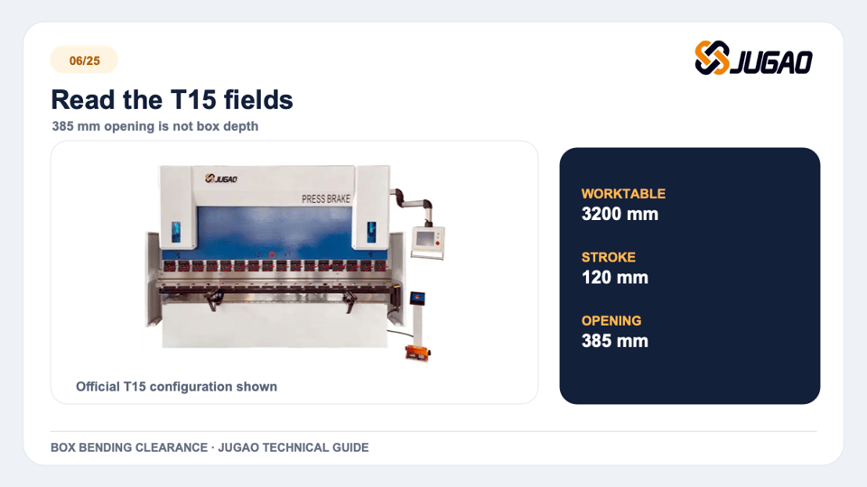
The official T15 page lists the following public fields. Each describes one part of the machine—not the complete installed-tool envelope of a finished box. The published 125TON/3200 T15 configuration lists 1250 kN nominal pressure, 3200 mm worktable, 2600 mm between columns, 320 mm throat depth, 120 mm ram stroke and 385 mm maximum opening. These are distinct fields, not the net space around an installed punch, die, holder and partly formed box. Confirm the order configuration on the JUGAO T15 product page and in the quotation.
- Worktable length is not a guaranteed turning length.
- Throat depth is not a finished box-depth limit.
- Ram stroke is travel, not installed-tool clearance.
- Maximum opening height is not maximum box depth.
125TON / 3200 T15
Four bends.
Four new envelopes.
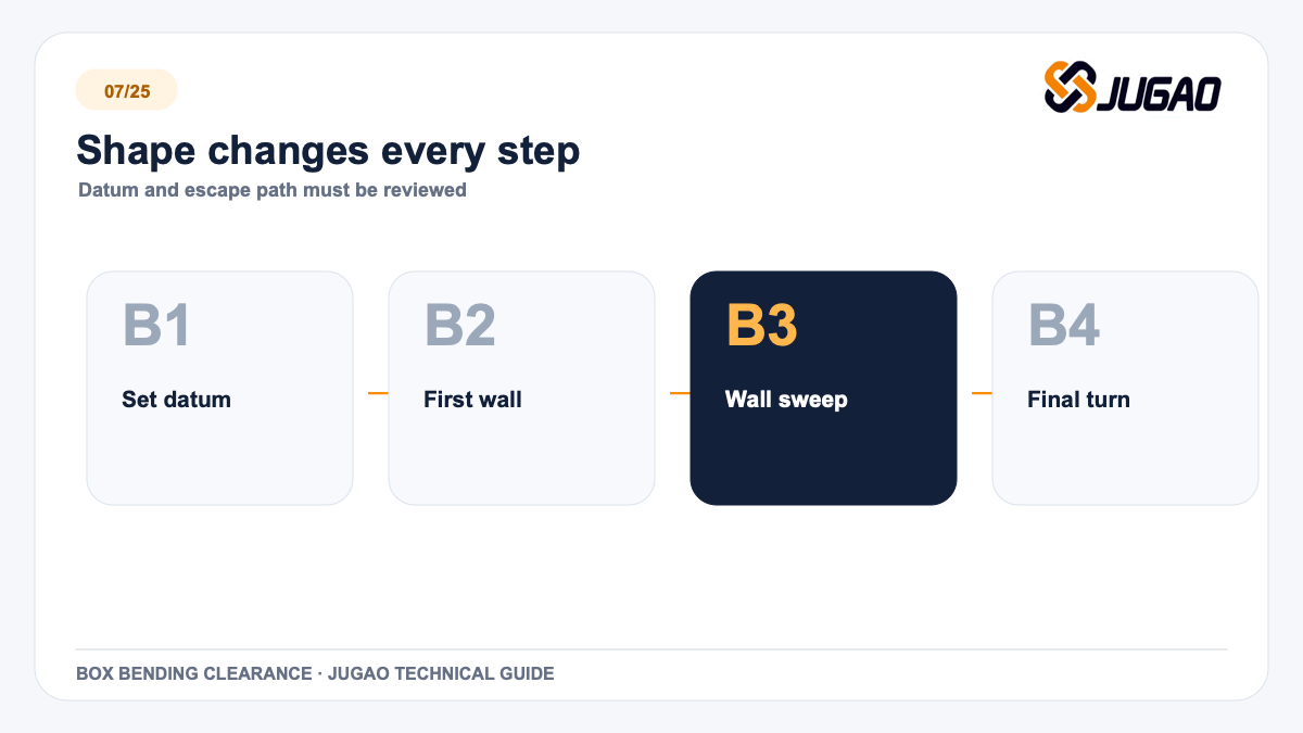
Every bend changes the part’s shape, datum and way out. Treat the timeline as a supplier review sheet. A sequence is feasible only if each intermediate shape can enter the station, be located, form without contact, return, rotate and exit. Review those movements with the actual machine and tool cross-sections. A clean final profile alone cannot prove the path.
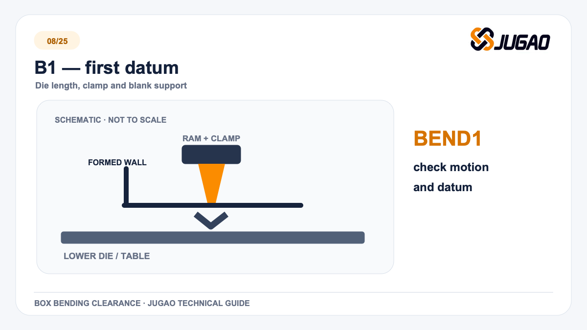
Load & set
Confirm the line reaches the effective die length. Check blank, tool, clamp, table, support and first datum. The blank must reach the effective tool station without hitting a column, holder, table or support. Confirm that the chosen bend line is fully supported and that the first backgauge datum is stable. A short flange may need a separate support check.
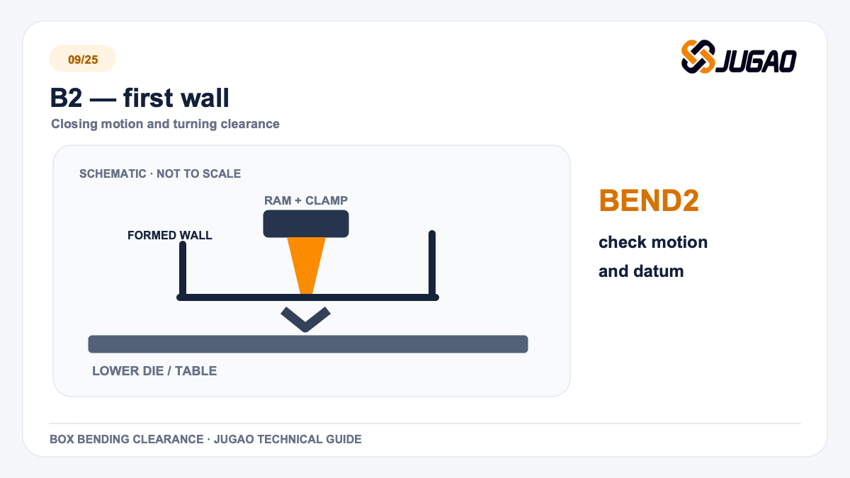
Turn & reset
Check the first flange during closing and turning. Reconfirm holes, short edges and support. After B1, the new flange changes how the part rests and where fingers can touch. Trace its travel on approach, through closing, on ram return and during the turn for B3. Check nearby holes and reliefs so they do not become unreliable gauge points.
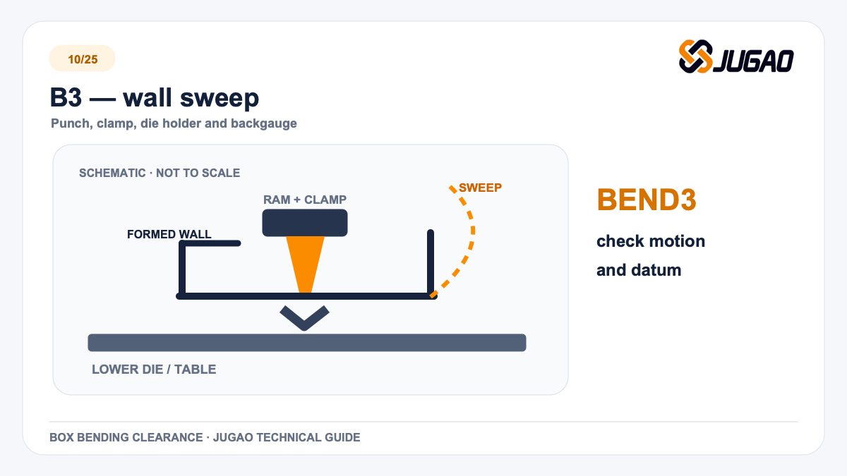
Watch the sweep
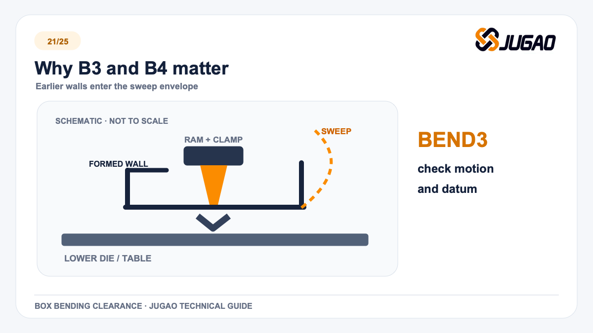
Track the formed wall against punch, slider, clamp, die holder, table, extensions and backgauge. At B3, previously formed walls can sweep upward toward the upper tool, ram and clamp while the lower edge approaches the die holder or table. Check the whole travel envelope, not only the position at bottom dead center. See WILA’s box-bending guidance for the tool and opening relationships that require review.
Find the way out
Check springback and final rotation. Forming clear does not guarantee removal clear. At B4, include springback, upper-tool withdrawal and the final rotation in the model. A box that forms successfully may still be trapped around the punch or between supports. Specify an unloading direction and check it against the actual fixture arrangement.
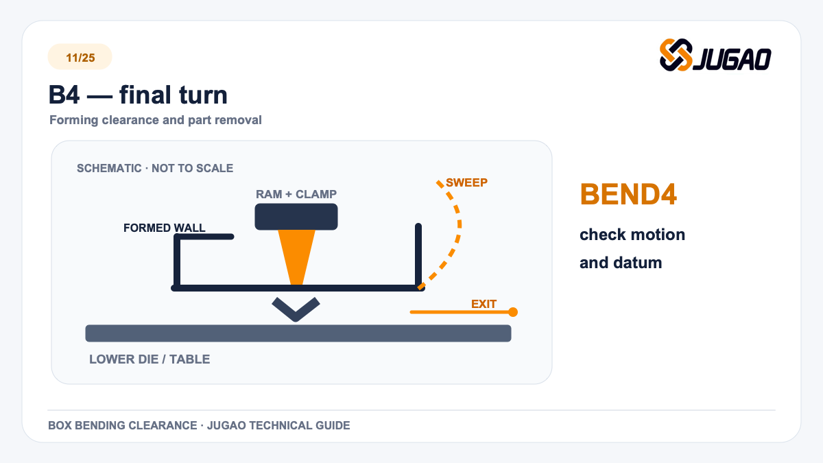
Watch the wall sweep through the machine.
WILA identifies the opening, tool height, die-holder height, punch shape and length, extensions and die contour as part of the box-bending review. The quoted opening, punch height, die-holder height, punch profile and length, extensions and die contour interact. There is no reliable universal multiplier from box depth to required punch height. Use the exact installed-tool model and record the tightest clearance at each stage, following WILA’s box-bending checklist.
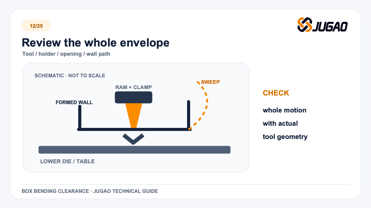
One collision can stop the job.
Change the tool.
Re-run the motion.
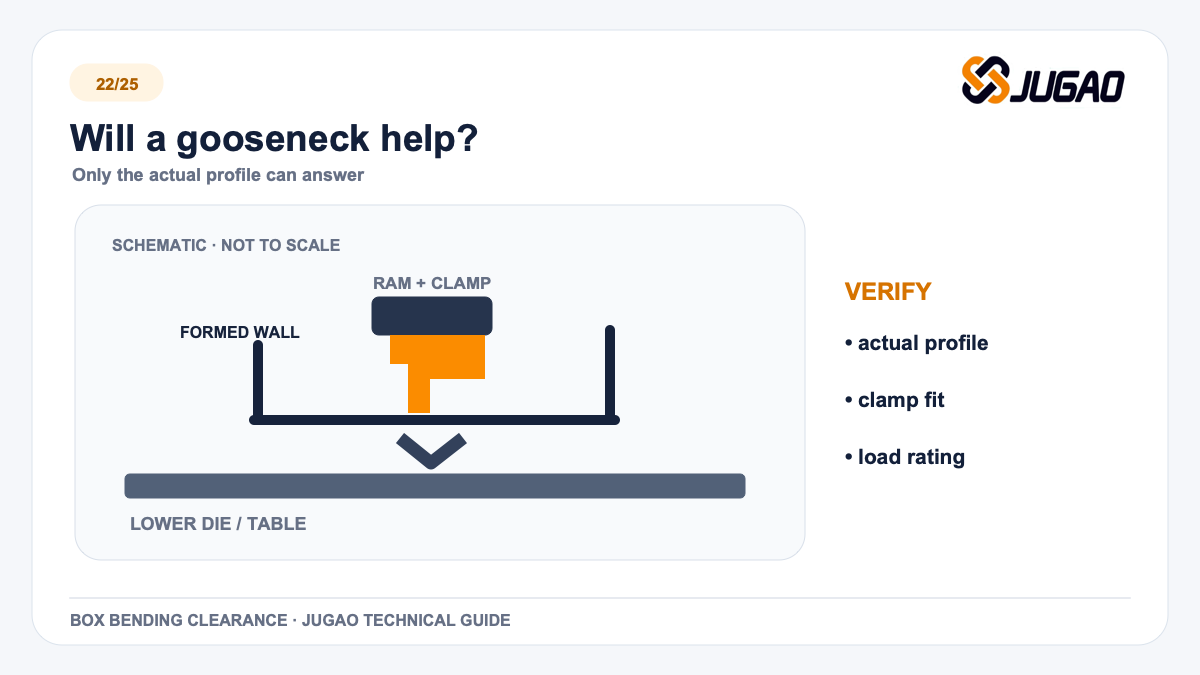
A gooseneck punch, taller punch, extension, segmented die, new sequence or new backgauge datum can change the envelope. None is a guarantee. Change one assumption at a time, then repeat B1–B4 and removal checks. A local tool relief might help one wall while reducing support or creating another collision. The purchase list must name every required tool and interface; the public T15 page does not establish that a special punch or segmented die is included.
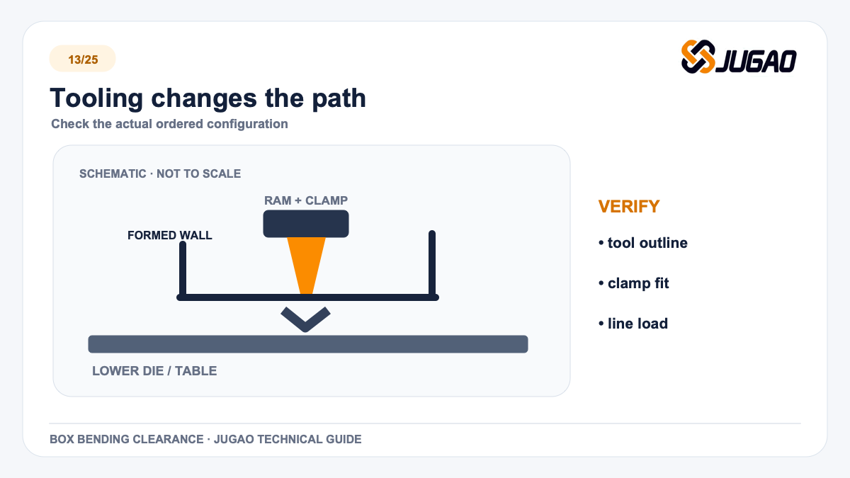
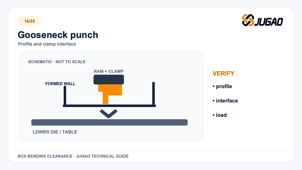
Gooseneck
May create local relief. Confirm profile, clamp interface, working height and load. A gooseneck can create space for a return flange, provided its real cross-section clears the moving wall. Ask for its tool number, working height, clamping interface and permitted load. The shape shown in a generic illustration cannot certify a specific order.
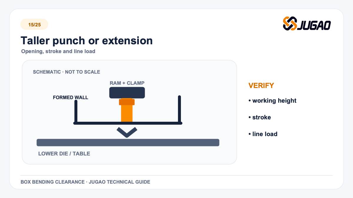
Raised tool
Consumes opening and stroke. Check interface and permitted line load. Raising the punch or adding an extension changes the net opening and stroke available to load and unload the part. Confirm the assembly height, clamping fit and permitted line load as a system. Re-run the approach and removal paths after any height change.
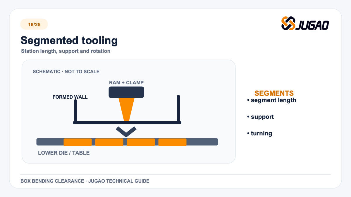
Segmented die
Can open a station. Verify segment length, support and rotation. A segmented station can leave a gap through which a box wall passes. Specify segment lengths and placement on the selected tool, and check support along the bend line. The gap may solve one collision while moving another wall into a clamp or support.
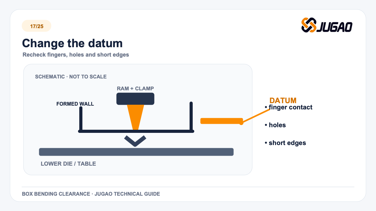
New datum
May solve one contact and create another around holes or short edges. The backgauge must contact a repeatable feature after every reorientation. If a hole, corner relief or short return interrupts the nominal edge, choose and document a different datum. Verify the new finger position together with the tool and part envelope.
Bend-by-bend clearance record
| Stage | Part state and movement | Tool / machine clearance | Datum and support | Recorded result |
|---|---|---|---|---|
| B1 | Flat blank: load, locate, bend and withdraw | Effective tool length, column, clamp, table | First finger contact and short-flange support | Pass / collision / data missing: ______ |
| B2 | First wall: approach, close, return and rotate | Punch, die holder, gauge fingers, support | New edge or feature used as datum | Pass / collision / data missing: ______ |
| B3 | Two formed walls: full upward sweep | Ram, upper tool, clamp, die holder, table | Repeatable datum after turning | Pass / collision / data missing: ______ |
| B4 + exit | Final wall: springback, return, turn and unload | Tool relief and path past support / frame | Last contact point and safe extraction route | Pass / collision / data missing: ______ |
- Record the input: drawing and CAD revision, material grade, thickness range, inside radius, bend angle and tolerances.
- Record the setup: quoted machine configuration plus punch, die, holder, clamp and extension part numbers and sections.
- Record the evidence: views for approach, bottom, return, turning and removal, with the limiting clearance identified.
- Close with a sample: actual material and tooling, agreed dimension and surface checks, and written acceptance by the parties.
Public information is the beginning.
Order data closes the loop.
| Area | Public reference | Order-level evidence still required |
|---|---|---|
| Machine | 1250 kN / 3200 / 2600 / 320 / 120 / 385 | Configuration, machine reference section and installed-tool clearance |
| Tooling | Standard dies and option/combination references | Punch, die, clamp, holder, extension and segment IDs/sections |
| Simulation | Delem DA-66T describes sequencing and collision detection | Actual controller, axes, libraries, CAD revision and screenshots |
| Part | No customer box result is published | B1–B4 sequence, backgauge contacts, support, removal and sample record |
WILA, SSAB and Delem support the process explanation. They do not prove a particular JUGAO order has passed. WILA’s collision review explains why tool data and handling space matter; SSAB’s flange guidance addresses short-edge support. A controller may help plan a candidate sequence, but the Delem DA-66T feature description does not establish any feature on this T15 order. None of these sources is a test result for a buyer’s part.
Make the supplier answer
the motion question.
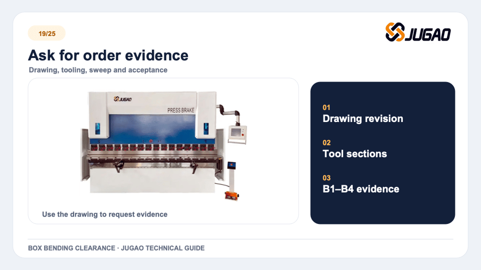
Ask for evidence against the drawing—not a generic statement that the machine is “suitable”. Send the released CAD and drawing revision, material and thickness range, surface and tolerance requirements, preferred open side and batch constraints. Request the quoted machine configuration, exact tool and clamp sections, B1–B4 screenshots, backgauge contacts, load check, support and unloading plan, and a representative sample acceptance record.
Clarity before the first bend.
Does 385 mm mean a 385 mm-deep box?
No. It is a catalogue opening field, not installed-tool clearance or a finished-box limit. For the cited T15, 385 mm is the published maximum opening height. Installed tools occupy space and the formed walls move during bending; subtracting box height from 385 mm does not give a usable clearance. Ask for the installed-tool section and motion review.
Why are B3 and B4 high risk?
Earlier walls sweep upward into the machine and tooling, while final rotation can trap the finished box. The first walls exist by B3, so they sweep through spaces that were free for the flat blank. B4 can also make extraction difficult after the stroke. Inspect approach, forming, ram return, turning and removal as separate states.
Will a gooseneck punch solve it?
Only the actual profile, interface, working height and load rating can show whether it helps. It may, when the actual tool relief surrounds the return without overloading the punch or violating the clamp interface. Verify its catalogue profile against the drawing and re-check the entire sequence. A generic gooseneck label is insufficient.
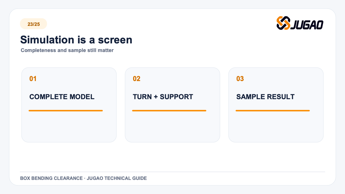
Can automatic collision detection approve the job?
No. Model completeness, support, turning and physical sample acceptance still require review. Simulation is a useful screen when machine, holders, tools, part revision and backgauge setup are accurate. It does not replace a support and handling review or a sample made from representative material. Save assumptions with the result.
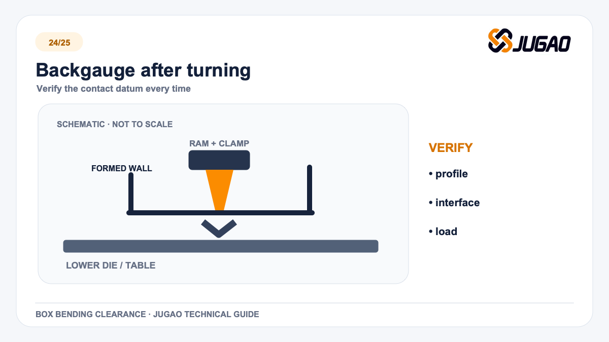
What must be checked about the backgauge?
Record the actual finger contact and datum after every turn, including holes and short edges. At every turn, record which finger touches which edge, the available contact length and the risk posed by holes or reliefs. A workable first datum does not automatically remain available after the first flange is formed.
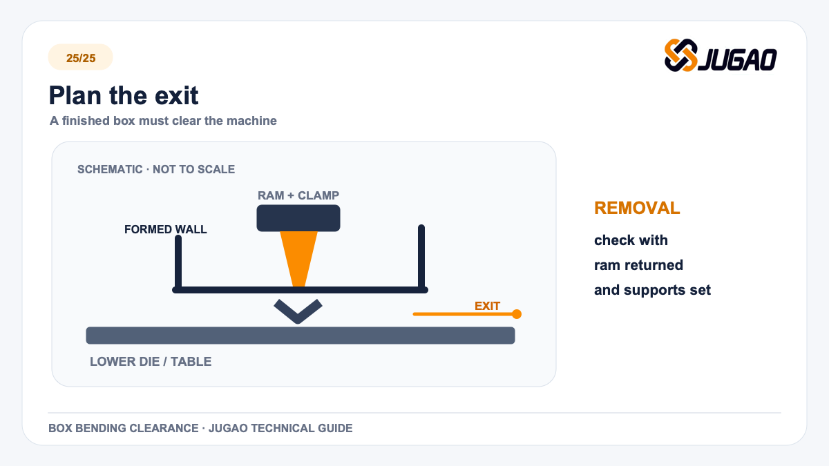
Why check removal separately?
A part can clear the tool during forming and still be trapped against a clamp, table, support or frame. The exit path is its own clearance check. Show how the operator releases, tilts or rotates the box after the last bend without striking the upper tool, die holder, support, table or frame. Include that movement in the sample review.
What if the box has a very short flange?
Contact Us