 Get a quote
Resources
From Laser-Cut Blank to Bent Part
JUGAO / PROCESS ENGINEERING / BLOG 08
One part. Two measurement states. One agreed release.
A part can be reviewed across cutting and forming when the released part data, flat pattern, bend sequence and sample inspection criteria all match. Control those inputs together first; then verify the blank and formed part against requirements the design team and fabricator have agreed.
- ReleaseMatch the finished model, drawing and DXF revision.
- MapConnect every flat feature to the formed geometry.
- ReviewCheck holes, bends, tools, orientation and removal path.
- First-offCut and form a representative sample from agreed inputs.
- AcceptMeasure both states and sign the agreed record.
One part definition across three files
Give the finished STEP model, 2D drawing and flat-pattern DXF the same part number, revision and release date. A file name alone is not a revision-control system: identify the released versions and make superseded files unmistakable. If the files disagree, stop for clarification and an approved revision instead of letting the shop choose which geometry to follow.
State file authority in the release note. A practical arrangement is for the approved STEP model to control nominal finished 3D shape, while the signed 2D drawing controls material, datums, dimensions, GD&T and inspection requirements. The drawing or purchase agreement should say what happens if the model and drawing conflict. The DXF describes the intended flat blank; it does not silently override finished-part requirements.
Name the owner of blank development. If the buyer supplies the DXF, do not assume it was developed for the fabricator’s material, thickness, inside radius, tools or bend allowance. If the fabricator develops or revises the flat, state that responsibility, agree the development method and approval path, and release the resulting DXF at the same revision as the finished definition.
Confirm file authority and blank-development responsibility before cutting.
Table 1 / STEP, drawing and DXF authority
| File | Role to state at release | Question to close before cutting |
|---|---|---|
| Finished STEP | Nominal finished 3D shape when explicitly designated as controlling. | Which revision is approved, and how are conflicts with the drawing resolved? |
| 2D drawing | Material, datums, toleranced dimensions, GD&T, inspection state and acceptance requirements. | Which dimensions apply flat, and which apply after forming? |
| Flat-pattern DXF | Cut profile and feature locations for the released flat state. | Who developed it, from which material/process inputs, and who approves a change? |
Table 1. File authority and blank-development responsibility to establish at release.
Table 2 / Release package checklist
| Release item | Must identify | Do not infer |
|---|---|---|
| Part identity | Part number, revision, release date and supersession status. | File authority from a file name alone. |
| Material definition | Grade, condition, nominal thickness and traceability route. | Material behavior from a generic DXF. |
| Forming definition | Bend ID, direction, angle, inside radius and development method. | An uncalibrated K-factor, radius or tool assumption. |
| Inspection release | Datums, measurement state, method, sample quantity and disposition. | A default tolerance, pass/fail result or unspecified standard. |
Table 2. Release checklist; approved project documents control actual values.
Put development assumptions on the record
In sheet-metal development, bend allowance (BA) is the bend arc measured along the neutral axis. SOLIDWORKS help shows flat-length expressions of A + B + BA and A + B − BD, and discusses BA/BD, K-factor and bend-table approaches.[3] These are development methods, not a universal K-factor table or a JUGAO process guarantee. Before approving the DXF, agree material grade and condition, thickness, bend angle, inside radius, forming method, tooling assumptions and who owns the final calculation.
Use dimensions to describe both the condition and the measurement state. Identify which dimensions belong to the laser-cut flat, which belong to the formed part, and which must be checked after forming. A dimension that is clear in a flat view may not be an adequate acceptance definition for the finished geometry.
GD&T gives teams a language for communicating design intent on engineering drawings and digital models; it does not fill in this part’s default tolerances. ASME’s public description identifies that role for Y14.5, but the project still needs an approved drawing and explicit acceptance requirements.[4]
Flat blank · laser-stage checks
hole shape / position ▭ S1
slot / orientation B1 · bend line / direction →
Formed state · part acceptance
angle / inside radius
Check final H1-to-bend location and fit
Review holes and slots with the bend
Holes, slots and cut-outs placed too close to a bend line may distort during forming. WILA’s public guidance discusses RotaBend tooling and bottom bending as possible approaches; it says bottoming can reduce deformation and improve consistency, not that it eliminates distortion in every part.[5]
Do not convert that guidance into a universal hole-edge distance. WILA points readers to a separate minimum-distance guide that must be requested; its public page does not establish one fixed distance for every material and process. The research report also records conflicting published rules of thumb with different assumptions and measurement origins, so this article does not repeat or calculate a fixed spacing value.
Review the feature, material, thickness, bend radius, angle, actual tool geometry and forming method together. Ask what the hole or slot does in the assembly and which finished condition matters: size, shape, position, profile, hole-group relationship or clearance to another part. A center-to-line number alone may not describe the required function after forming.
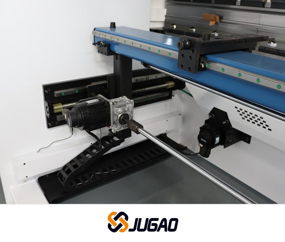
Table 3 / Near-bend feature risk review
| Design or process question | Risk to evaluate | Options to review | Approval evidence |
|---|---|---|---|
| Is a hole, slot or cut-out near a bend? | Feature shape or location may change during forming. | Move it; change shape or orientation; consider approved relief; review a suitable tool/process; or machine a critical feature after bending where access and datums allow. | Approved revision and representative sample verification. |
| Does the feature have an assembly or appearance function? | A flat-state check may not confirm formed-state function. | Define the finished requirement and measurement state; check fit or assembly function where specified. | Agreed datums, method and acceptance requirement. |
| Will tooling or process change? | A prior sample may no longer represent the process. | Review actual tooling and forming method against the released geometry. | Documented review and renewed approval when needed. |
Table 3. Design and process questions for a feature near a bend line.
Table 4 / Inputs to review before a feature change
| Input to review | Why it matters | Evidence to request |
|---|---|---|
| Feature function | Assembly, sealing, fastening or appearance may control the formed requirement. | Functional datum, mating condition or approved drawing note. |
| Material and thickness | Forming response and distortion are process-dependent. | Material certificate or traceable batch record. |
| Radius, angle and tool geometry | Actual strain and contact conditions change the result. | Tool section, V-opening, radius and setup record. |
| Alternative process | Moving, relieving or post-machining may affect strength, access or datum strategy. | Approved revision plus representative sample evidence. |
Table 4. Inputs to review before changing a near-bend feature. It intentionally provides no universal hole-edge distance.
- Relocateif function allows
- Reviseshape or relief
- Review processtool and forming method
- Machine laterif access and datums allow
WILA’s air-bending guidance says minimum flange length depends on the V-opening, lower-die shoulder radius and bend angle. Treat those relationships as tooling guidance to evaluate with the actual part, not as a universal flange guarantee.[6]
A peer-reviewed 2009 study by Farsi and Arezoo examined holes on bending surfaces in HSLA sheet using V-shaped dies while varying die angle, die width and sheet thickness. Its abstract reports that those variables affect springback and bending force.[7] Keep the evidence within those HSLA/V-die conditions; it does not establish a universal hole-spacing rule or a result for a JUGAO machine.
Read the whole drawing package before the first cut
Make the released package answer the questions a programmer, operator and inspector will each face. Include:
- Part number, revision, release date and a way to trace the applicable material batch or certificate.
- Material grade and condition, nominal thickness and applicable thickness requirement; where relevant, texture or rolling direction, protective film and visible surfaces.
- Finished dimensions, functional datums, GD&T, measurement state and the dimensions that must be accepted after forming.
- An ID, direction, angle, inside radius and development assumption for every bend; distinguish inside and outside dimensions and datum faces.
- Hole, slot, cut-out, relief and edge geometry, with each feature’s function and whether its size or location applies flat or formed.
- Approved requirements for outline, cut edges, burr or dross, blank flatness, formed geometry, fit and assembly function, as applicable.
- Inspection tools or method, datum setup, support condition, sample quantity, record retention and nonconformance disposition—all agreed, not inferred.
ASME Y14.5 can help teams communicate design intent; it is not a default tolerance schedule for a purchase order. Name the drawing revision, applicable standard and acceptance requirements in the contract or release package rather than assuming that a machine specification supplies them.[4]
Follow a controlled route from blank to accepted part
- Freeze revision and authority. Match the released STEP, drawing and DXF by part number, revision and date. Record which file controls finished shape, which controls tolerances and who owns blank development.
- Map flat features to formed geometry. Identify each bend line, datum and finished face. Mark holes and slots near bend zones, visible surfaces and features that may be difficult to measure after forming.
- Inspect the laser-cut blank. Check outline, critical coordinates, hole and slot geometry, edge condition, burr/dross and flatness only against agreed requirements and a stated method.
- Review every bend with the real setup. For each operation, record material orientation, locating face, tool, already formed features, flips, access and removal path. Simulation can support review; it does not prove a physical sample conforms.
- Make and measure a representative first-off. Use the agreed material, thickness and traceable batch. Record setup and adjustments; inspect blank and formed states separately against the approved plan.
- Approve and freeze the process record. Record values, methods, responsible people and the acceptance decision. Reassess approval if material, thickness, tool, radius, program, sequence, drawing or DXF changes.
- Freeze the released files
- Map features to formed geometry
- Inspect the flat blank
- Review actual bend setup
- Measure the first-off
- Approve and record
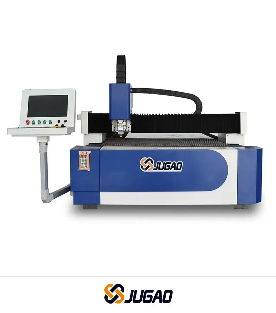
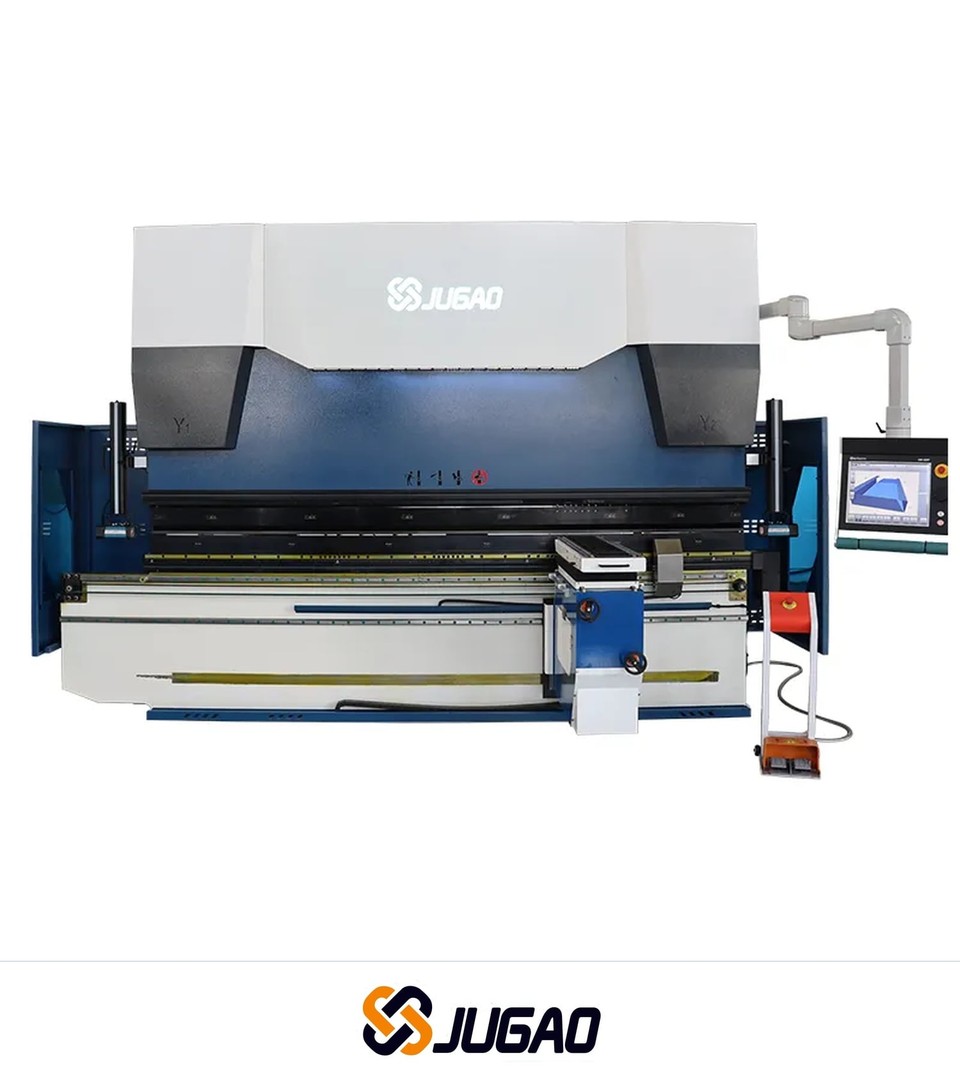
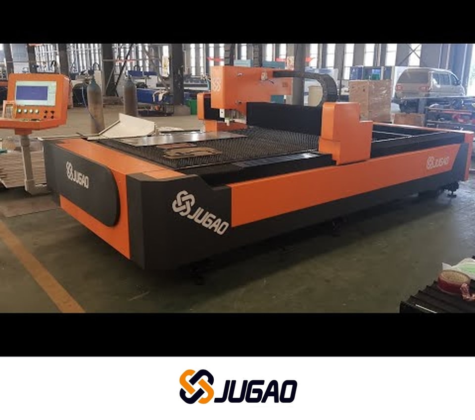
JUGAO’s ER3015-2000W product page and 125TON/3200 T15 page are manufacturer equipment descriptions, not independent test reports or proof that a specific part was tried.[1][2] The laser page contains an unresolved conflict: general text says “German fiber laser source,” while the parameter table lists MAX. Its axis-positioning figures have no listed test conditions supporting use as cut-feature or formed-part tolerances. Press-brake fields such as nominal pressure, table length, throat, stroke and opening do not establish the selected tool envelope or part acceptance. Keep these pages as equipment context, separate from the part’s inspection requirements.
Machine specifications provide context, not part acceptance
JUGAO’s ER3015-2000W product page and 125TON/3200 T15 page provide equipment context, not proof that a specific part was tried or accepted.[1][2]
ER3015-2000W laser cutting machine
ER3015-2000W / Published laser fields
| Published field | Value on product page | Use and boundary |
|---|---|---|
| Model / working area | ER3015-2000W / 3000 × 1500 mm | Manufacturer listing; equipment context. |
| Laser generator / power | Parameter table: MAX / 2000 W | The page’s general copy says “German fiber laser source,” which conflicts with the MAX field. Do not choose between them; confirm the ordered source with the supplier. |
| X/Y positioning accuracy | ±0.02 mm | Machine-axis field only. The page does not specify measurement method, standard, area, load or compensation conditions; this is not a cut-feature or formed-part tolerance. |
| X/Y repeat positioning accuracy | ±0.02 mm | Machine-axis field only; the same test-condition limits apply. |
| Maximum moving speed / maximum acceleration | 120 m/min / 1.5 G | Published machine fields, not part-quality results. |
ER3015-2000W laser product-page fields; report verification date: October 26, 2026. The page does not document a part-specific trial or acceptance test.
125TON/3200 T15 press brake
125TON/3200 T15 / Published press-brake fields
| Published field | Value on product page | What still needs part-specific review |
|---|---|---|
| Nominal pressure | 1250 kN | Selected tools, setup and forming operation. |
| Working-table length / distance between columns | 3200 mm / 2600 mm | Part placement, support, clearance and bend sequence. |
| Throat depth | 320 mm | Access and part orientation for each operation. |
| Ram stroke / maximum opening height | 120 mm / 385 mm | Required travel, tool stack and formed-part clearance. |
| X/Y-axis positioning accuracy (JUGAO configuration specification) | 0.02 mm | JUGAO configuration specification for the applicable ordered configuration; confirm axis scope and test conditions with the supplier. Not a part or bend-product tolerance. |
| X/Y-axis repeat positioning accuracy (JUGAO configuration specification) | 0.05 mm | JUGAO configuration specification for the applicable ordered configuration; confirm axis scope and test conditions with the supplier. Not a part or bend-product tolerance. |
125TON/3200 T15 press-brake product-page fields; report verification date: October 26, 2026. The 0.02 mm positioning and 0.05 mm repeat-positioning figures above are the JUGAO configuration specification for the applicable ordered configuration. The public product page does not state these figures or their test conditions; confirm applicability, axis scope and test method with the supplier. They are machine-axis indicators, not cut-feature, bend-line or finished-part tolerances. The page also does not specify a part’s tool section, V-opening, radius, clamping, bend sequence, trial bend or acceptance record.
Separate blank checks from formed-part checks
Before production, agree the characteristic, drawing reference, stage, datum/support setup and measurement method for every required check. The matrix below is a planning aid, not a filled inspection report. Add limits, sample quantity, readings and disposition only from the approved drawing or agreement.
Table 5 / Laser-stage versus formed-part inspection
| Stage | Possible check | Measurement state / method to define | Acceptance basis |
|---|---|---|---|
| Laser blank | Outline and critical hole/slot coordinates | Flat; identify datums and support/locating method. | Released flat requirements or approved inspection plan. |
| Laser blank | Hole shape, slot shape/orientation, cut-outs and edge geometry | Flat; state the feature measurement method. | Drawing or agreement for the blank state. |
| Laser blank | Cut-edge condition, burr/dross and flatness | State inspection method, viewing condition and support. | Only the agreed edge and flatness requirements. |
| Formed part | Overall dimensions, flange dimensions and bend angle | Formed; specify datums, orientation and measuring setup. | Released formed-part drawing requirements. |
| Formed part | Inside radius or profile; hole-to-bend relationship | Formed; define reference faces/datums and method. | Approved dimension, profile or functional requirement. |
| Formed part | Fit, assembly function, twist or flatness where required | State fixture/support, mating condition and method. | Customer-approved requirement or agreed assembly check. |
Table 5. Separate laser-stage and formed-part inspection checks by measurement state and approved basis.
Table 6 / First-off responsibility and approval
| Role | Before cutting | At first-off | At approval |
|---|---|---|---|
| Design / buyer | Confirm controlling files, function, datums and revision. | Review deviations and requested changes. | Sign the released acceptance basis. |
| Fabricator | Confirm material, development method, tools and sequence. | Record setup, adjustments and traceability. | Freeze the approved process record. |
| Quality | Confirm methods, support, sample quantity and records. | Measure blank and formed states separately. | Record disposition and retained evidence. |
Table 6. Responsibility view for a representative first-off; it does not replace the customer’s approved quality plan.
- Outline and feature coordinates
- Hole / slot shape and edges
- Agreed flatness check
- Overall and flange dimensions
- Angle, radius / profile
- Fit and feature relationship
Blank first-off inspection worksheet
Keep the fields empty until a released requirement and actual reading exist. There are no default tolerances, sample quantities, measured results or pass/fail decisions in this worksheet.
Table 7 / Blank inspection worksheet — no preset limits or results
| Stage | Characteristic / feature ID | Drawing ref. / datum | Method / setup | Sample qty. | Limit | Measured value | Disposition |
|---|---|---|---|---|---|---|---|
| Laser blank | |||||||
| Laser blank | |||||||
| Laser blank | |||||||
| Formed part | |||||||
| Formed part | |||||||
| Formed part |
Table 7. Blank first-off worksheet; add requirements and readings only from the approved plan.
Frequently asked questions
Is there one safe hole-edge distance for every bend?
No universal distance is established by the public WILA page. Review the feature, material, thickness, radius, angle, tool geometry and forming method together, and confirm the approved design on a representative sample.
Does the buyer’s DXF automatically control the blank?
It controls the cut blank only when the release package assigns that authority and the responsible party has agreed the development inputs. A DXF based on different material or bend assumptions may not develop to the required finished shape.
Can a machine positioning figure be used as a part tolerance?
No. Equipment axis positioning is not a stated cut-feature or formed-part tolerance unless a relevant test method and acceptance requirement support that claim. Use the part drawing and approved inspection plan.
Does simulation approve the first part?
No. Simulation can help review sequence and access, but it does not replace physical first-off measurement against released requirements.
Discuss the drawing before release
When a hole, bend, material callout or file responsibility is unclear, resolve it in the drawing package before the first-off. To ask JUGAO about a drawing or machine configuration, use JUGAO’s enquiry page.[8] Any part-specific feasibility or acceptance conclusion still needs agreed part data, actual setup and inspection evidence.
Sources
- JUGAO, ER3015-2000W laser cutting machine product page. Manufacturer listing; source wording conflicts between general copy and table. No listed positioning test conditions establish a part tolerance. Report verification date: October 26, 2026.
- JUGAO, 125TON/3200 T15 press-brake product page. Manufacturer listing; machine fields do not document a part-specific setup, trial or acceptance. Report verification date: October 26, 2026.
- SOLIDWORKS Design Help, “Bend Allowance and Bend Deduction”. 2022 help page; cited for the visible BA definition and expressions, not a calibrated JUGAO process.
- ASME, “Dimensioning and Tolerancing”. Public description of Y14.5-2018 (R2024); not a project tolerance schedule or an unreviewed clause.
- WILA, “Bending with cut-outs near the bend line”. Public application guidance; identifies risk and methods but publishes no universal distance or guarantee. Page checked October 26, 2026.
- WILA, “Air bending”. Tooling-maker guidance connecting minimum flange length with V-opening, lower-die shoulder geometry and bend angle. Page checked October 26, 2026.
- Farsi & Arezoo (2009), peer-reviewed paper. Limited to the report’s summary of HSLA sheet and V-shaped die experiments; full text was restricted.
- JUGAO, Contact Us. Enquiry link only; not technical evidence.
© 2026 JUGAO. All rights reserved. Except for materials credited to third parties, the original text, graphics and design of this article are owned by JUGAO. Unauthorized reproduction or redistribution is prohibited.
Related
Keep
reading.
 Comparison of Laser Welding Results and Application Scenarios Across Different Materials
 How to Choose Between Air-Cooled and Water-Cooled Laser Welding Systems
 Understanding Punching Machines: Principles, Types, and Selection
 How can one effectively follow the installation guidelines for a pipe-bending machine?
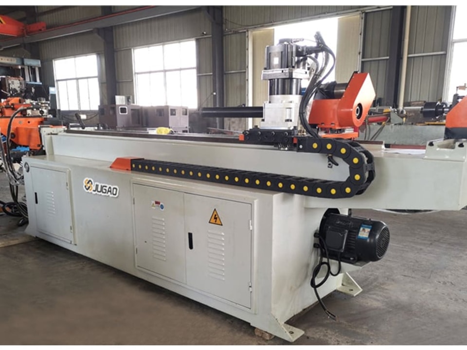 Tube Bend Quality After the First Sample: How to Check Wrinkles, Ovality and Wall Thinning
 Can Your Plate Roll Form This Cone? A Drawing-to-Sample Buying Checklist
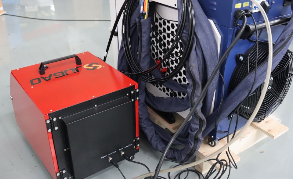 For which types of products is an automatic wire-feeding laser welding machine suitable?
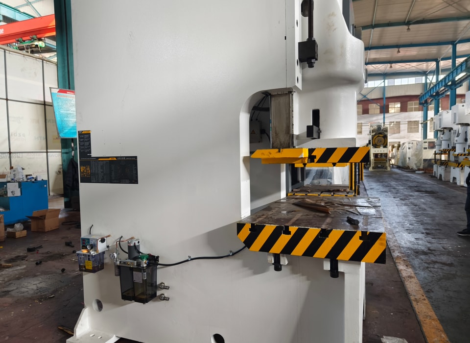 What Are the Latest Punching Machine Trends and Technological Breakthroughs?
 What Triggers Punching Machine Noise and How Can You Quieten It?
 What factors influence the replacement cycle of wear parts in a pipe-bending machine?
 Beyond price, what key parameters should you consider when purchasing welding equipment?
 4 Common Methods for Inspecting Weld Quality
Engineering review
Send a drawing.
Get an engineer.
Standard selections answered within 4 hours. Parts outside the rules get a written process review within 24 hours.
- Part drawing: DXF, DWG, STEP or PDF
- Material and thickness
- Longest bend or cut length
- Yearly volume
Write to info@ntjugao.com or message the factory on WhatsApp +86 132 2211 1178.
Drawings (DXF, DWG, STEP, PDF): attach them to an email to info@ntjugao.com, quoting your name.