
How to Choose a CNC Press Brake: Start with Your Part Drawing
2026-09-17

A practical engineering brief for buyers, production managers and engineers
Start with the part. Then choose the press brake.
The short answer: begin with the actual part drawing, material, bend length, radius and flange, forming process and bend order. Compare those inputs with the machine envelope, tooling and backgauge sequence. Published tonnage and working-table length are screening information only. Before purchase, obtain written confirmation for the actual workpiece and accept the configuration with a representative sample.
01 / Begin with the workpiece
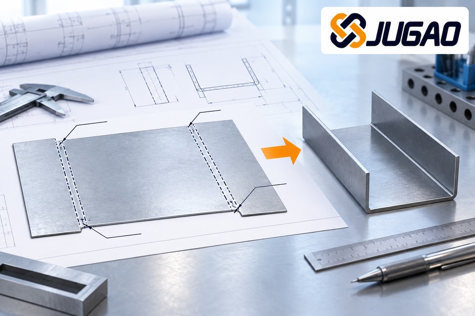
A machine name cannot replace a part brief
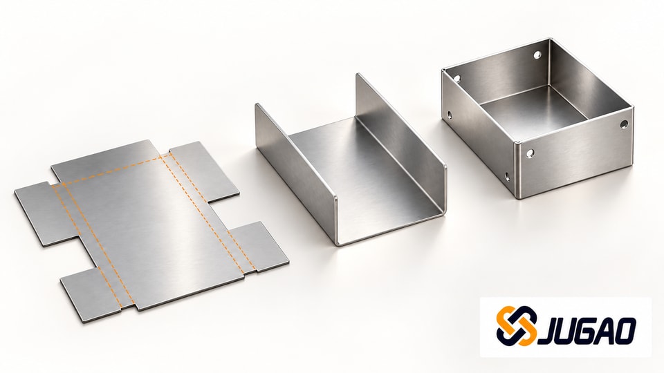
A bracket, cabinet side, enclosure, channel or long panel may all arrive at a factory as “sheet-metal work,” but the difficult dimension is different in each case. A small bracket may be limited by the shortest flange and tool access. A deep box may be limited by the throat and opening. A long panel may fit the table yet become awkward to rotate, support or unload. A drawing-led request turns those differences into engineering questions before a quotation becomes a purchase order.
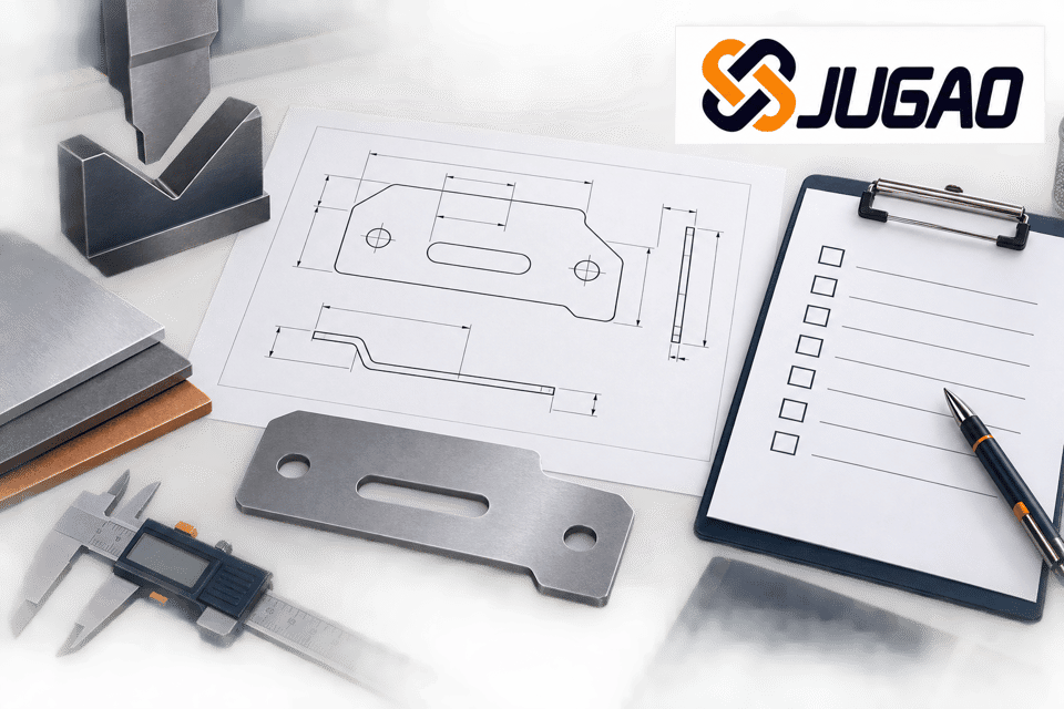
Prepare two drawings if possible: one representative part and one difficult part. Include the released 2D drawing, a 3D STEP file when available, material standard and grade, thickness range, visible surface, angle tolerance, bend sequence and expected batch mix. If a hole, return, hem or wall sits close to a bend, mark it. The supplier should see the feature that may collide, not only the overall length.
Keep the forming route explicit. A flat blank with straight bend lines belongs in a press-brake discussion. A cylindrical shell or continuous rolled arc is a different forming problem. A tube centerline and bend radius are not a substitute for a sheet-metal drawing. This article stays focused on CNC press-brake selection.
- 01Separate “published” from “promised.” A product page can show a configuration’s nominal values; a purchase decision needs a written, part-specific confirmation.
- 02Separate “controller” from “machine.” Programming functions can help plan a bend, but the frame, tools, axes and supports still define what can happen on the shop floor.
- 03Separate “force example” from “force guarantee.” A catalog chart explains parameter interaction; the supplier’s calculation must use your actual material and tools.
02 / Read the mechanical envelope
3200 mm working table and 2600 mm between columns
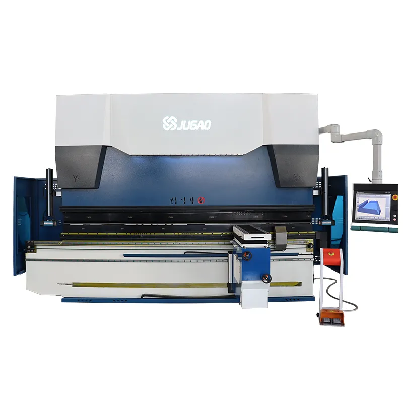
The JUGAO 125TON/3200 T15 product page lists a 3200 mm working-table length and 2600 mm distance between columns. Treat those values as two different filters. The table length describes the published working surface; the column distance describes the frame opening. Neither number alone proves that any 3200 mm workpiece can complete every bend and be removed safely.
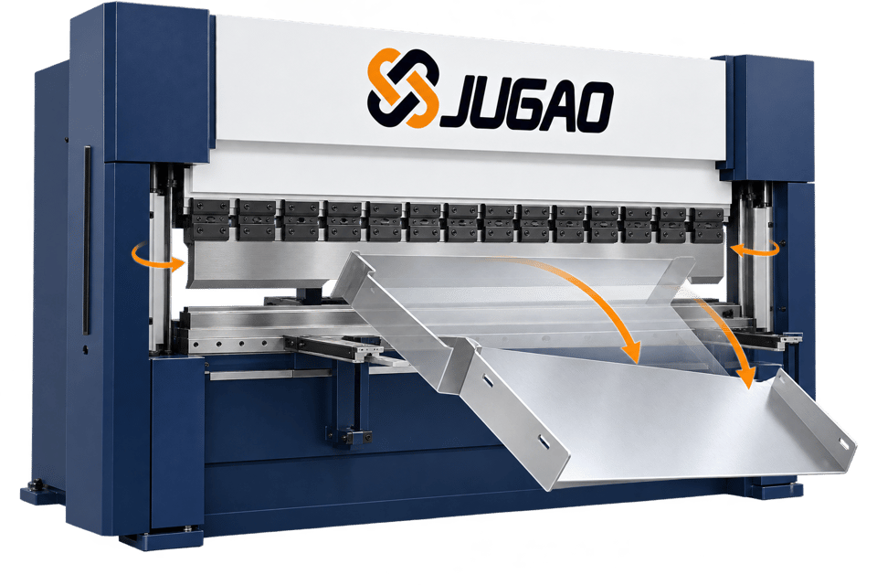
| Published value for the 125TON/3200 T15 configuration | What it helps you screen | What it does not prove | RFQ question |
|---|---|---|---|
| 1250 kN nominal pressure | The nominal pressure stated by the product page. | It does not guarantee the force for every grade, thickness, bend length, V-die or process. | Can you calculate the required load for my material, bend and tools, and state the assumptions? |
| 3200 mm working-table length | Whether the longest straight bend line is within the published table length. | It does not prove frame clearance, complete bend sequence, support, rotation or unloading. | Where is the usable length for my tool segmentation and support arrangement? |
| 2600 mm distance between columns | Whether the workpiece and movement need a frame opening larger than the listed gap. | It is not an absolute maximum bend length and is not a complete box-part envelope. | Can you review the part’s formed walls and handling path between the columns? |
| 320 mm throat depth | Whether a deep return or flange can reach the tool area without frame interference. | It does not decide the tool’s actual clearance or the part’s full rotation path. | Can you show a clearance view for the deepest feature? |
| 120 mm stroke; 385 mm maximum opening | Available ram movement and opening for tool stack and loading. | They do not confirm every punch/die height, return, wall or setup. | Which opening and stroke remain with the quoted tools installed? |
Why the table length is only a first screen
A 3200 mm table may be long enough for a single straight bend but not enough for the way the part is supported. A segmented die can change the usable layout. A rear finger may reach one datum but not another. A formed flange can move the center of gravity and change how an operator must rotate the part. Those are not headline specifications; they are drawing and setup questions.
Ask the supplier to use the actual released drawing, not a generic rectangle. The review should show the part in its bend order, with the selected punch, V-die, backgauge fingers and any front support or crowning option. If the part is large, include a handling sketch showing where the operator stands and how the part is removed.
Why 2600 mm is not a maximum bend claim
The distance between columns is a frame dimension. It can help identify a collision risk, but it does not automatically define the maximum length that can be bent, because the tool layout, material overhang, load distribution, support and part shape also matter. Never rewrite “2600 mm between columns” as “2600 mm maximum bending length.”
The safe procurement question is conditional: does this particular configuration, with this tool set and this bend sequence, support this particular part? That answer belongs in the quotation, the simulation review or the sample protocol.
03 / Force, material and process
Why 1250 kN is not your part’s required bending force
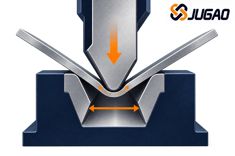
The JUGAO page states 1250 kN nominal pressure for this published configuration. Nominal pressure identifies the machine’s headline capacity, but required bending force depends on the actual workpiece and process. Material strength, thickness, bend length, V-opening, tool geometry and whether the operation is air bending or bottoming all matter. The correct procurement record is a written calculation with assumptions, not a tonnage label alone.
WILA catalog example: 22 metric tons/m × 3.2 m = 70.4 metric tons; 15 metric tons/m × 3.2 m = 48 metric tons.
Conditions: WILA chart reference for mild-steel 90° air bending; material thickness 2 mm; V=12 mm or V=16 mm; illustrative uniform straight bend length 3.2 m. This is a catalog-level calculation, not JUGAO measured data, not a JUGAO selection calculation and not a production guarantee. Confirm material batch, tooling, process, allowable machine/tool load and compensation with the supplier. Do not turn the example into a claim that 1250 kN is automatically sufficient.
Open the WILA catalog reference to review the chart’s stated units and conditions. WILA also notes that bottoming can require several times the force of air bending; the process must therefore be stated rather than assumed.
04 / Tool geometry is part geometry
V-opening, radius and minimum flange move together
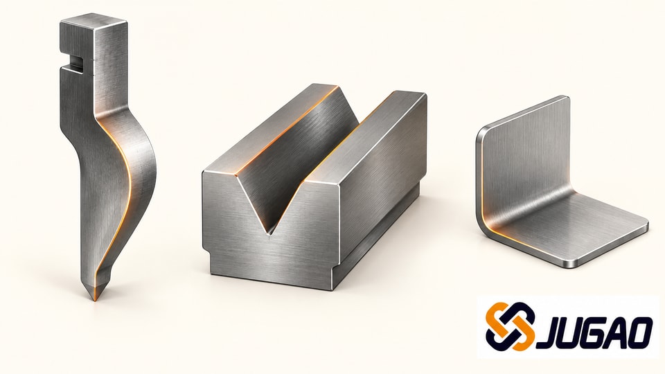
Confirm the selected tools and part dimensions against the released drawing.
WILA’s air-bending guidance describes how the V-opening influences the formed inside radius, force, marking and minimum flange, and notes that changing the opening changes flat-pattern development. For steel air bending, WILA gives a starting range of about 6–8 times material thickness for the V-opening. That is an engineering starting point, not a universal setup rule for every alloy, strength, angle, punch, die or bottoming operation.
The drawing should therefore identify the inside radius and shortest outside flange, not only the finished angle. If the flange is short, the die may not support the geometry as expected. If the radius is cosmetic or load-sensitive, the tool and material condition must be named. If the blank has holes close to the bend, the tool nose and backgauge approach may become part of the fit check.
WILA’s catalog geometry table is explicitly a soft-steel, 90° air-bending reference. Under that condition, V=12 mm corresponds to a minimum outside flange B of 8.6 mm and inside radius ri of 1.8 mm; V=16 mm corresponds to B of 11.5 mm and ri of 2.4 mm. These are reference values, not JUGAO commitments or measurements of a buyer’s batch.
| WILA reference condition | V-opening | Minimum outside flange B | Inside radius ri | 2 mm chart force | Use in an RFQ |
|---|---|---|---|---|---|
| Soft steel, 90° air bending | 12 mm | 8.6 mm | 1.8 mm | 22 metric tons/m | Reference discussion only; ask for part-specific confirmation. |
| Soft steel, 90° air bending | 16 mm | 11.5 mm | 2.4 mm | 15 metric tons/m | Reference discussion only; do not treat as a JUGAO test result. |
| Other material or process | To be selected | To be calculated | To be calculated | To be confirmed | State grade, strength, thickness, angle, tool and process before approving. |
SSAB explains springback as elastic recovery and notes that it increases with steel strength and with the die-width-to-thickness ratio. Its page is explicitly applicable to SSAB products, so do not generalize its product-specific recommendations to every steel source.
Punch style and nose radius · V-die opening and segment plan · material assumption · calculated load per metre and total load · allowable tool/machine load · expected springback correction · surface-contact requirement.
05 / Controller, backgauge and sequence
DA-66T can plan the bend; the quote defines the hardware
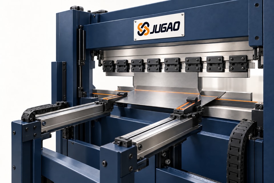
Delem describes the DA-66T as offering 2D programming with automatic bend-sequence calculation and collision detection, plus a full 3D machine setup with multiple tool stations and feedback on product feasibility and handling. Those functions are useful because a drawing can be tested as a sequence rather than treated as isolated angles.
They do not establish the axis count or options on a specific JUGAO order. A controller name does not prove which backgauge axes, finger layout, travel, supports, servos, machine model, software licence, crowning or sensors are included. The practical boundary is simple: controller documentation explains what the control can do; the quotation must identify what the machine actually contains.
Request a written axis list and use the drawing’s datums to test it. Can the fingers reach the first bend, then clear the return for the next bend? Can the operator support a long panel without losing the datum? Does the 3D setup include the actual tool stations and collision geometry? Those answers matter more than an axis count without a part context.
For a second JUGAO configuration to compare, see the JUGAO DA-66T press-brake listing. Its advertised axes are page information for that product, not a T15 configuration or an order guarantee.
Backgauge is a datum system
Evaluate fingers, travel, supports and repeatability against the actual bend sequence. “More axes” is not automatically “better” if the finger arrangement cannot reach the part’s datums.
Simulation is a review tool
Use 2D/3D programming and collision checking to expose a problem early, then confirm that the simulation model matches the quoted frame, tools, supports and options.
06 / A richer decision path
Six gates from drawing to purchase
Use the same released part data at every gate. If the material, tool or process changes, the calculation and sample plan must change with it.
Is the forming route right?
Confirm a flat sheet, straight bend lines and the intended press-brake process. Keep pipe bending and plate rolling outside this selection path.
Does the part fit the envelope?
Check working length, column gap, throat, opening, stroke, tool stack, wall height and rotation/unloading path.
Does the force calculation match?
State grade, strength, thickness, bend length, V-opening, radius and air-bend/bottoming process. Request a written load calculation.
Does the tool support the geometry?
Compare V-opening, minimum flange, radius, punch nose, segment plan, holes and visible surfaces with the drawing.
Can the sequence be repeated?
Review backgauge datums, fingers, supports, collisions, operator access and the exact axis/options list.
Can the sample prove it?
Agree the sample material, drawing revision, tools, bend order, measurements, tolerance and acceptance record before the trial.
07 / Copy this into an RFQ
A buyer’s configuration worksheet
A detailed RFQ makes the supplier’s answer comparable. Leave no hidden assumptions about “standard” tools, axis counts or material. The blank result column is intentional: it is for the supplier’s written response.
08 / Make suitability testable
Use the sample to turn paper fit into evidence
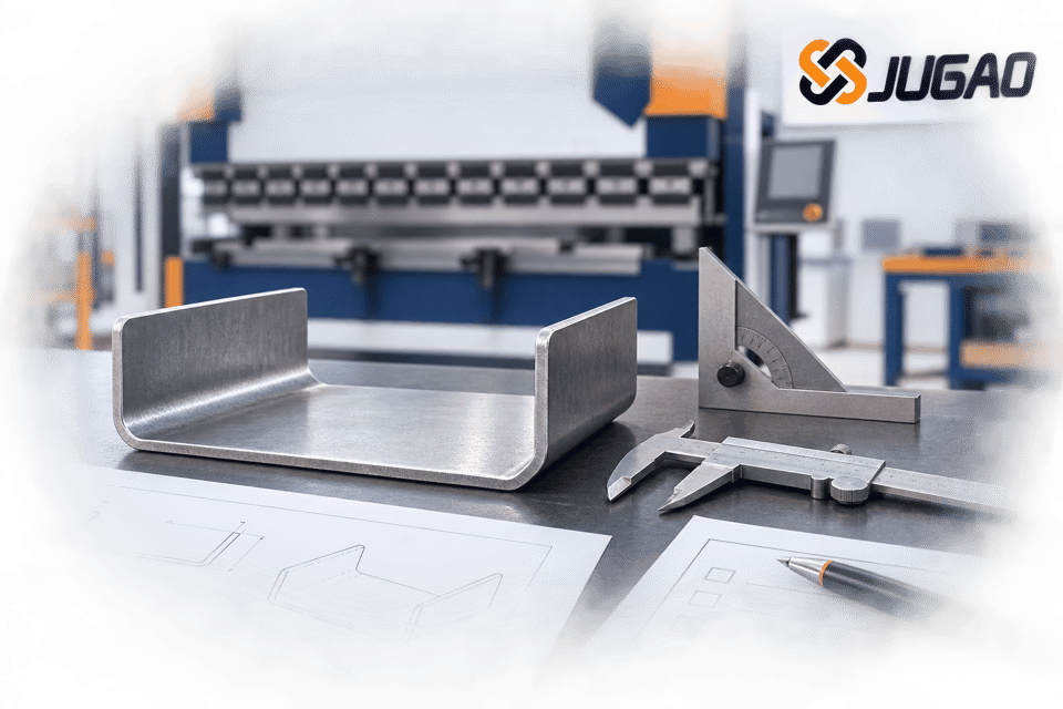
A supplier can quote a machine without knowing whether it will produce the buyer’s exact part. A sample protocol closes that gap. Use the released drawing, actual material and the quoted tools. Record the result; do not replace the result with a generic accuracy or cycle-time claim.
| Acceptance item | Record before the trial | Buyer/supplier result |
|---|---|---|
| Drawing package | 2D revision, 3D STEP, critical dimensions and inspection points | ________________ |
| Material traceability | Standard, grade, batch/strength range, thickness and tolerance | ________________ |
| Machine setup | Exact model, frame, table, tools, axes, supports and software/options | ________________ |
| Tool setup | Punch nose, V-die, opening, segment layout, interface and allowable load | ________________ |
| Bend sequence | Program revision, datums, backgauge fingers and collision review | ________________ |
| Geometry result | Angle, flange, length, diagonals, openings and measurement method | ________________ |
| Springback record | Unloaded angle, correction used, material and tool condition | ________________ |
| Surface result | Allowed marks, scratches, pressure lines and named visible faces | ________________ |
| Operator and site | Training, guarding review, power, delivery scope and handover documents | ________________ |
| Approval | Buyer representative, supplier representative and date | ________________ |
OSHA’s presence-sensing guidance is US-specific safety background. It describes particular safeguarding applications and requirements; it is not a global compliance statement, does not establish that a machine is “OSHA certified” and is not a substitute for the buyer’s site-specific risk assessment. US buyers should review the actual machine and operation with their safety lead.
Release the drawing
Freeze revision, material and critical dimensions.
Get assumptions
Require force, tool and axis details in writing.
Agree protocol
Set sample, measurement and acceptance rules.
Record result
Capture setup, correction and final unloaded angles.
Close the file
Approve the configuration and training record.
09 / Avoid expensive assumptions
Five procurement mistakes that a drawing can expose early
- 01Buying the headline tonnage. A nominal pressure number may look reassuring, but it does not include the material strength, V-opening, bend length or process that create the actual load. Ask for the calculation before comparing a machine to a drawing.
- 02Calling table length “part capacity.” A 3200 mm working table is not a promise that a 3200 mm box can be rotated, supported, bent through every step and removed without interference.
- 03Assuming the controller supplies the axes. DA-66T functions can support sequence and collision review, but the machine quote must still list the actual backgauge axes, travel, fingers, supports and options.
- 04Quoting a die before checking the flange. A V-opening changes force, radius, minimum flange and flat-pattern development. A generic “standard tooling” line is not enough when a short flange or visible face is critical.
- 05Testing the wrong material. A sample made from an easier substitute can hide springback, marking or load issues. Use the released grade, thickness and surface condition whenever the result is meant to approve the purchase.
10 / From quotation to production
What a complete handover package should contain
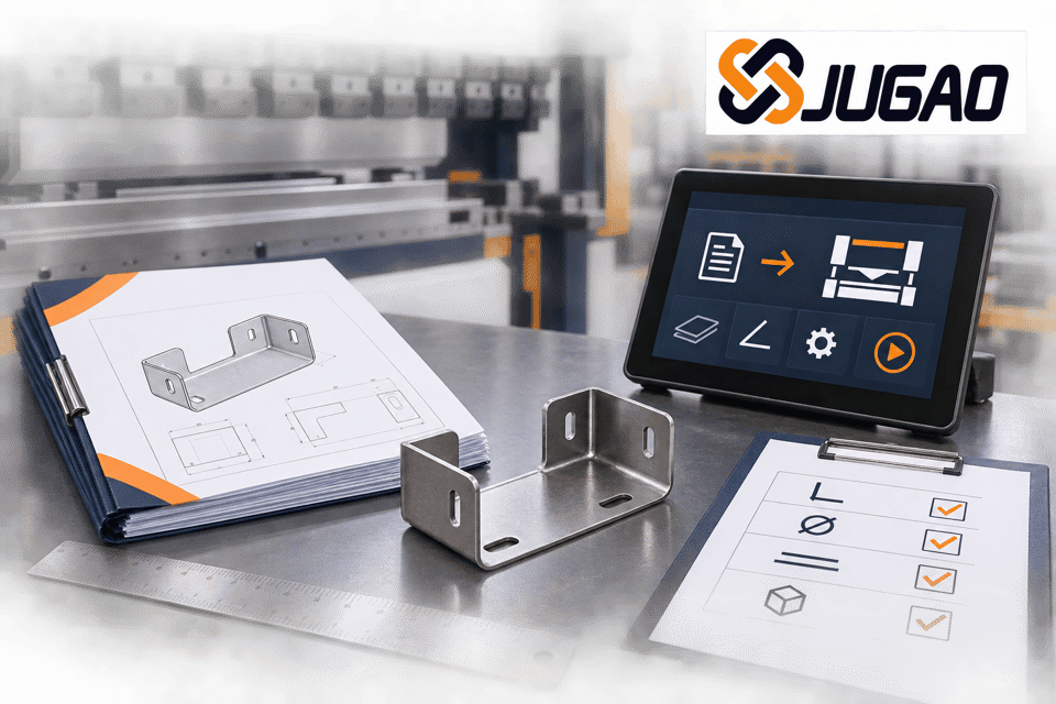
A press brake becomes useful when the engineering decision survives the move from a buyer’s spreadsheet to an operator’s setup. The handover should preserve the assumptions that made the sample work, while leaving room for the production team to document its own approved method.
| Handover layer | Recommended record | Why it matters |
|---|---|---|
| Part definition | Released drawing revision, 3D file, material specification and critical inspection points | Prevents an old revision or substitute material from being treated as the approved part. |
| Machine definition | Exact model, table and frame values, throat, stroke, opening, control, axes and included options | Preserves the configuration that was actually reviewed and purchased. |
| Tool definition | Punch, V-die, segment layout, interface, load limit and surface-contact requirements | Connects the drawing geometry to the setup that produced the sample. |
| Program definition | Program revision, bend order, datums, corrections and collision-review notes | Lets production understand which sequence and correction were accepted. |
| Quality definition | Angle, length, flange, diagonal, opening and cosmetic measurements with method | Turns “looks good” into a repeatable inspection record. |
| People and safety | Training record, guarding review, operating mode and site responsibilities | Separates machine delivery from the buyer’s obligation to assess the actual workplace. |
For an international purchase, keep units explicit in every document. The WILA example in this guide uses metric tons per metre and a 3.2 m illustrative bend; the JUGAO product page lists kN, mm, kW and kg. Do not silently convert or mix units when comparing a supplier calculation with an internal worksheet. Record the original unit, the converted unit if one is needed, and who checked the conversion.
Also keep a distinction between an engineering trial and a production-capability claim. One successful sample can show that a proposed setup works for that part, material and condition. It does not establish a universal accuracy, cycle-time, energy or service-life claim for every part. If those measures matter to the purchase, define a separate test method and acceptance threshold rather than adding an unsupported promise to the article or RFQ.
Questions before you request a quote
FAQ
Does a 3200 mm table mean I can bend a 3200 mm box?
No. The table length is one published dimension. The box still needs frame clearance, throat, opening, stroke, tool access, backgauge reach, support and an unloading path through its full sequence.
Is 2600 mm between columns the maximum bend length?
No. It is the listed distance between columns on the referenced configuration. Do not rewrite it as an absolute maximum bending length. Check the actual tool layout, overhang, load distribution and part shape.
Can 1250 kN be compared directly with the WILA example totals?
Not as a pass/fail conclusion. The WILA values are catalog-level references for stated mild-steel 90° air-bending conditions. The supplier must calculate the buyer’s actual material, tool, process and load assumptions.
Is 6–8 times thickness a mandatory V-die rule?
No. WILA presents it as a starting range for steel air bending. Material, strength, angle, tool geometry and forming process can change the appropriate opening.
Why does the minimum flange matter?
If the outside flange is too short for the selected V-die and punch geometry, the part may not seat or form as expected. Use the drawing’s shortest flange and compare it with the selected tool, not only a catalog rule.
Does DA-66T tell me the machine’s axis count?
No. It describes controller functions such as 2D programming, automatic sequence calculation, collision detection and 3D setup. The exact machine axis list and options belong in the JUGAO quotation.
How should I deal with springback?
Record the actual material grade and thickness, make a test bend, measure the unloaded angle and document the correction. SSAB’s linked guidance is specifically for SSAB products and should not be treated as universal material data.
What is the strongest next step?
Send one representative drawing, one difficult drawing, material data, bend sequence, tolerance and surface requirements. Ask for written force/tool assumptions, a complete axis/options list and a representative sample acceptance plan.
Build the quote around your part
Use the JUGAO bending-machine category to frame the product discussion, then submit the drawing package through the JUGAO contact page.
Sources and actual links used
- JUGAO 125TON/3200 T15 CNC press-brake specification — configuration-specific nominal pressure and mechanical dimensions.
- JUGAO bending-machine category — product-family context.
- JUGAO contact page — inquiry CTA.
- WILA air-bending guidance — V-opening, air bending, force and geometry discussion.
- WILA USA Catalog, page 140 — mild-steel 90° air-bending force and geometry reference table.
- SSAB springback guidance — elastic recovery and product-specific boundary.
- Delem DA-66T — 2D programming, sequence calculation, collision detection and 3D setup functions.
- OSHA Machine Guarding eTool — US-specific presence-sensing and safeguarding background.
Contact Us