 Get a quote
Resources
What factors should be considered when installing a hydraulic pipe-bending machine?
When clients ask me what exactly they need to pay attention to during the installation of a hydraulic pipe-bending machine, my first response is always: this isn’t just a matter of placing the machine on the floor and plugging it in. A proper installation is the deciding factor for the consistency of bending precision over the coming years, the overall lifespan of the machine, and the safety of its operation. Below, I’ll outline the key points that truly require close attention during the installation process.
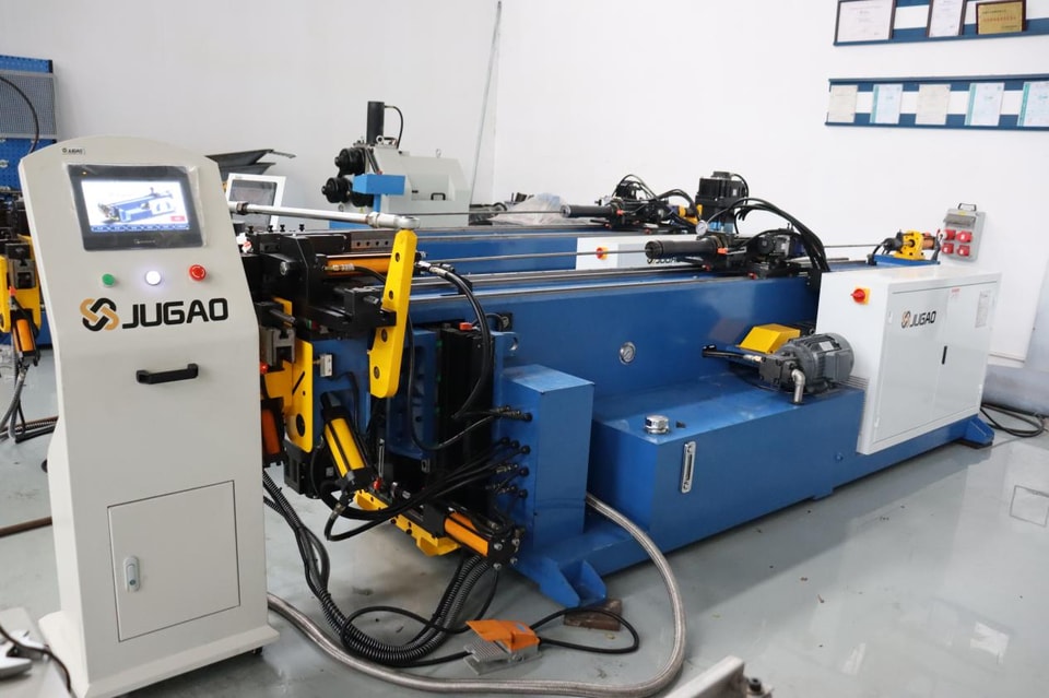
I. Flooring and Site Preparation: The First Hurdle
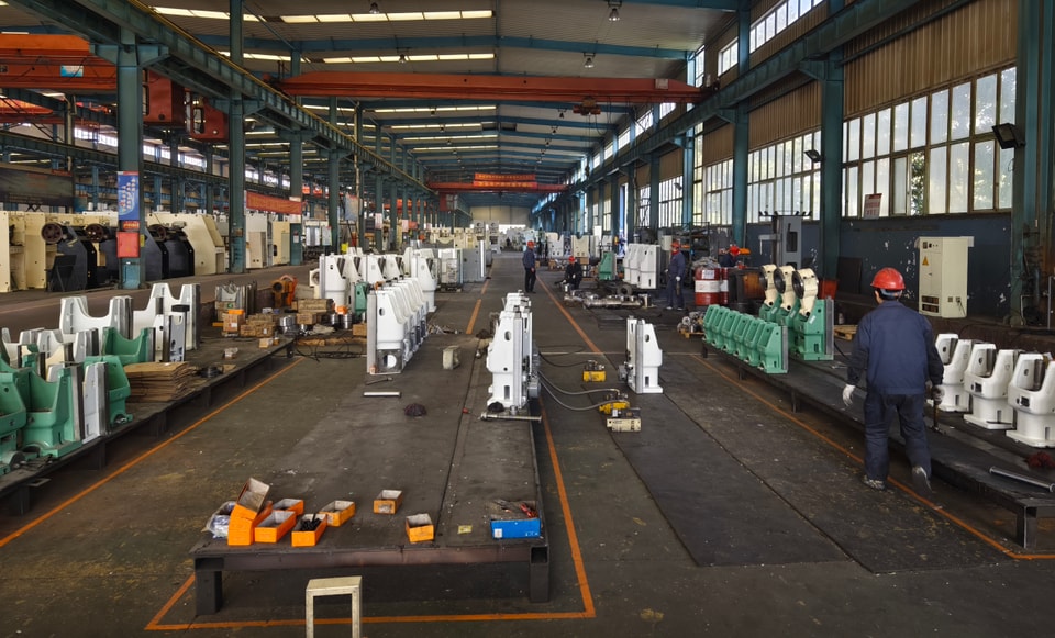
A hydraulic pipe-bending machine is a piece of heavy equipment that generates significant impact forces and dynamic loads during operation. The floor must have sufficient load-bearing capacity; standard, thin concrete flooring is often inadequate. For medium-to-large models, a reinforced concrete foundation is recommended. An uneven floor can cause the machine frame to deform, leading to inaccuracies in bending angles and premature wear on guide rails and bearings.
Space must also be planned in advance. Sufficient clearance should be left around the machine for loading and unloading materials, changing dies, performing routine maintenance, and allowing operators to move freely. Carefully mapping out material flow and personnel walkways will prevent bottlenecks during production.
II. Electrical and Hydraulic Connections: Getting It Right Is Essential
Incorrect power supply configuration is one of the most common issues encountered during installation. The voltage, frequency, and phase sequence must strictly match the specifications on the machine’s nameplate. Errors can lead to system alarms and shutdowns, or, more severely, motor overheating and damage to the control system. If you are unsure, consult a qualified electrician—do not attempt to wire the machine based on guesswork or personal experience.
Use only the hydraulic oil grade specified by the manufacturer, and ensure the reservoir is clean before filling. Air must be completely purged from the hydraulic lines; otherwise, you may encounter pressure fluctuations, excessive noise, and inconsistent bending precision during testing. Inspect every connection point, and ensure there are no leaks.
III. Alignment and Leveling: The Foundation of Precision
Once the machine is in position, leveling is critical. Use a precision spirit level to verify that the machine frame is level from multiple directions, and tighten the anchor bolts evenly in a diagonal sequence. Improper leveling creates uneven stress within the frame, which compromises the consistency of the bending angles.
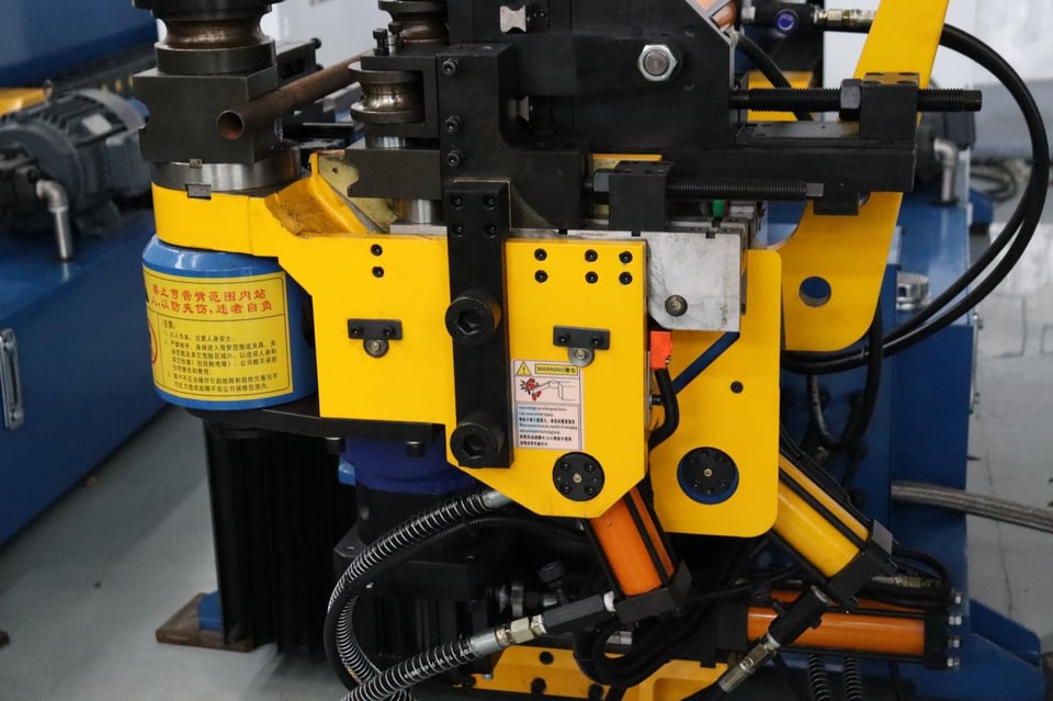
The bending head, clamping dies, pressure dies, and mandrel system must all be precisely aligned according to the manufacturer’s specifications. Misalignment can cause the pipe to wrinkle or deform, or result in inconsistent bending radii—issues to which thin-walled pipes are particularly sensitive.
IV. Parameter Configuration and Calibration
After the mechanical components are installed, configure the parameters within the control system. Follow the operation manual step-by-step to set axis limits, hydraulic parameters, and safety interlocks. Ensure that all position sensors, encoders, and pressure sensors are properly calibrated. Do not rush this step; calibration errors can accumulate over repeated bending cycles, making subsequent adjustments much more difficult.
V. Trial Run (Both No-Load and Under-Load)
Begin with a no-load run: listen for unusual noise, observe vibrations, and verify the stability of the hydraulic system. Once the no-load operation is confirmed to be trouble-free, proceed to a trial bend using a sample tube (under-load). Inspect the bend angle, radius, and surface quality, then fine-tune the bending speed, pressure, and compensation values based on the results. Only after the trial bend meets all specifications should you move on to mass production.
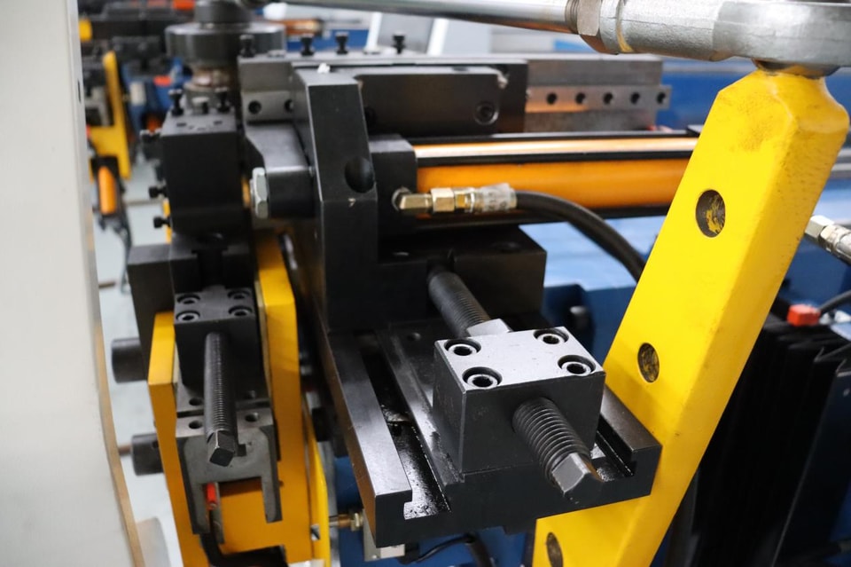
VI. Verification of Safety Devices
Test every safety device—including emergency stop buttons, light curtains, protective guards, and safety door switches. Pressing an emergency stop button must immediately halt all machine movements. The machine must not be able to operate while a safety door is open. While these features may not be used during routine operation, they are critical for ensuring safety in emergencies.
VII. Operator Training
Even the best-installed equipment is useless if the operators do not know how to use it. Schedule training as soon as installation is complete, ensuring operators understand basic machine operation, emergency stop procedures, and daily inspection requirements. Many early-stage malfunctions are linked to operator error; thorough training can help prevent a significant number of such issues.
The installation of a hydraulic pipe bending machine—covering the foundation, power supply, hydraulic system, centering, calibration, trial operation, safety, and training—is critical to future production. Investing an extra day during the installation phase can prevent days of downtime later on.
Related
Keep
reading.
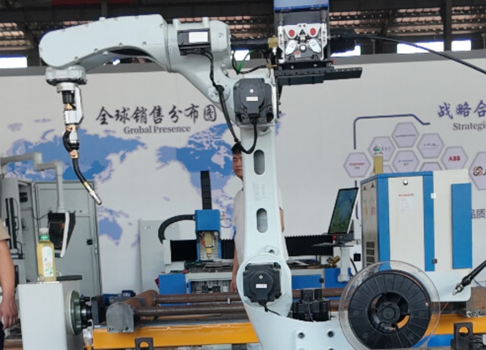 Comparison of Laser Welding Results and Application Scenarios Across Different Materials
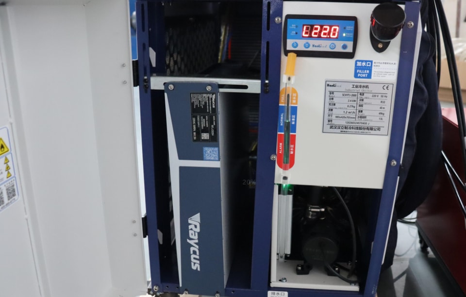 How to Choose Between Air-Cooled and Water-Cooled Laser Welding Systems
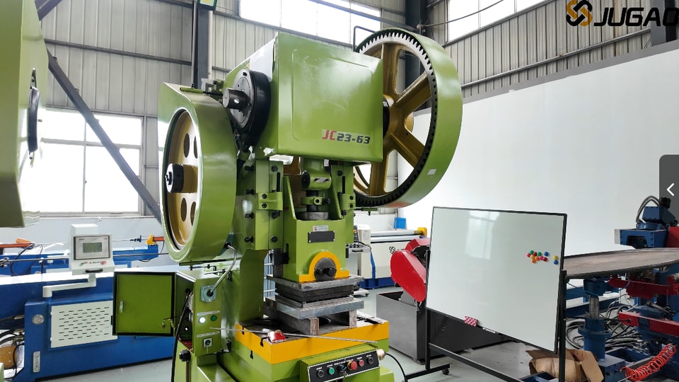 Understanding Punching Machines: Principles, Types, and Selection
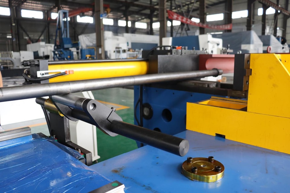 How can one effectively follow the installation guidelines for a pipe-bending machine?
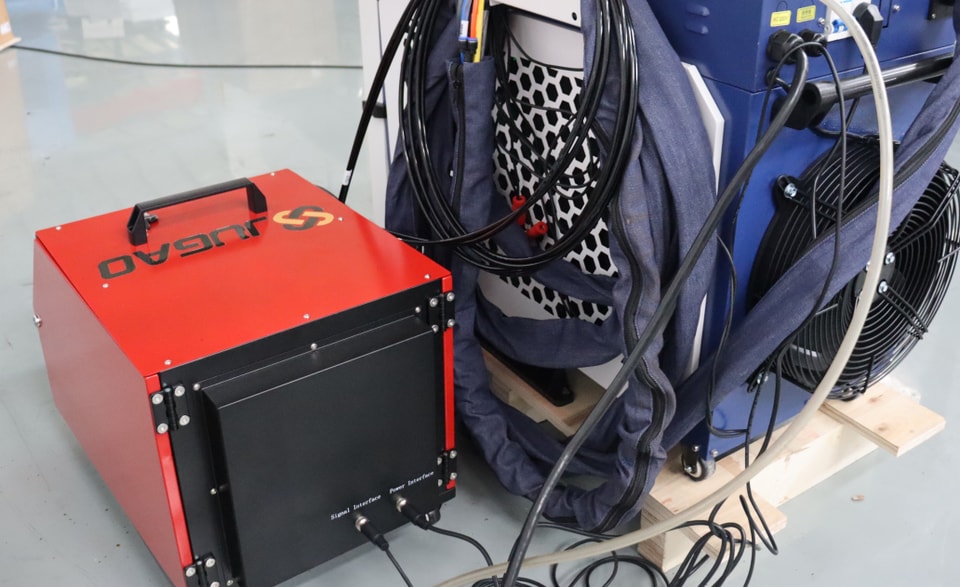 For which types of products is an automatic wire-feeding laser welding machine suitable?
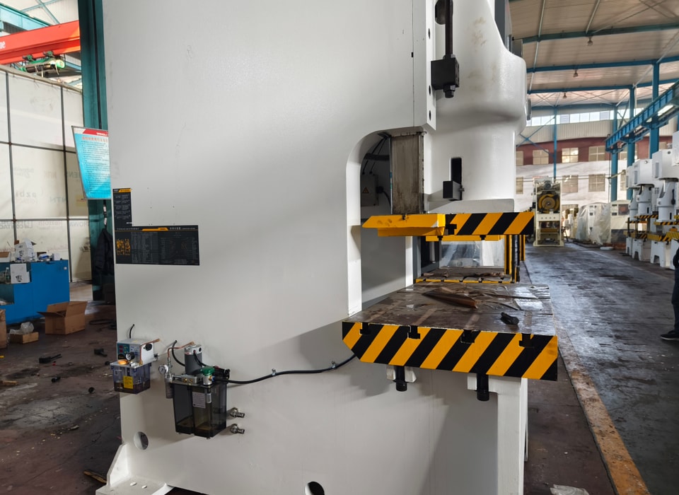 What Are the Latest Punching Machine Trends and Technological Breakthroughs?
 What Triggers Punching Machine Noise and How Can You Quieten It?
 What factors influence the replacement cycle of wear parts in a pipe-bending machine?
 Beyond price, what key parameters should you consider when purchasing welding equipment?
 4 Common Methods for Inspecting Weld Quality
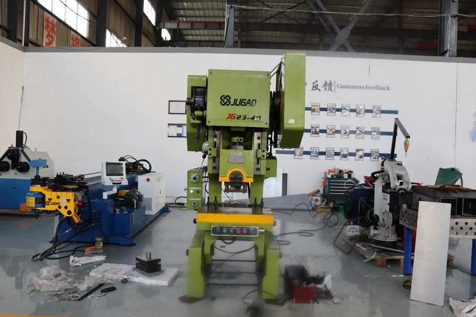 Selecting the Top Punching Machines for Small Workshops & Heavy Industry
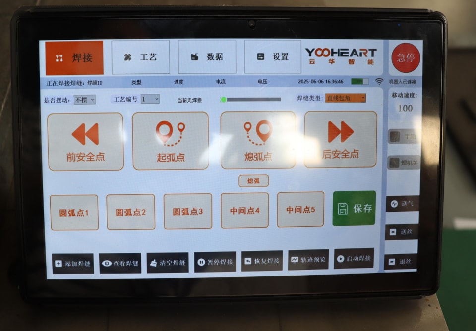 How do you set the welding path for a robotic laser welding machine? Can it perform precise welding on complex workpieces?
Engineering review
Send a drawing.
Get an engineer.
Standard selections answered within 4 hours. Parts outside the rules get a written process review within 24 hours.
- Part drawing: DXF, DWG, STEP or PDF
- Material and thickness
- Longest bend or cut length
- Yearly volume
Write to info@ntjugao.com or message the factory on WhatsApp +86 132 2211 1178.
Drawings (DXF, DWG, STEP, PDF): attach them to an email to info@ntjugao.com, quoting your name.