
What Causes Blackened & Scorched Edges in Fiber Laser Cutting
2026-09-22

Table of Contents
• Getting to Know Scorched and Blackened Cutting Edges
• What Exactly Are Scorched Edges?
• The Importance of Superior Edge Finish
• Root Triggers for Blackened or Scorched Laser‑Cut Edges
○ Mismatched Cutting Travel Speed
○ Over‑High Laser Output Power
○ Misaligned Focal Point
○ Inadequate Auxiliary Gas Pressure
○ Sub‑Standard Auxiliary Gas Purity
○ Clogged Nozzle or Contaminated Protective Optics
• Step‑by‑Step Diagnostic Workflow for Scorched Cutting Defects
○ Step 1: Confirm Base Material Properties
○ Step 2: Double‑Check Cutting Process Parameters
○ Step 3: Carry Out Nozzle Condition Inspection
○ Step 4: Check All Optical Assemblies
○ Step 5: Run Auxiliary Gas Circuit Validation
○ Step 6: Complete Test Cutting on Scrap Workpiece
• Proactive Guidelines to Avoid Scorched & Blackened Cut Edges
○ Keep Optical Parts Spotless
○ Keep Tabs on Auxiliary Gas Purity
○ Tune Process Parameters for Every Material Variant
○ Implement Periodic Preventive Servicing
• Frequently Asked Questions
○ What brings about black scorched edges while laser‑cutting stainless steel sheets?
○ Is insufficient gas pressure capable of generating black cut edges?
○ What is the suggested inspection & cleaning frequency for nozzle and protective lens?
• Final Summary
Blackened and scorched edges represent prevalent quality flaws in laser metal fabrication, which compromise visual appearance, machining precision and functional performance of finished laser‑cut components. If dark discoloration, heavy heat marks or charred borders frequently emerge on your machined workpieces, multiple underlying factors may be at play. This article breaks down major contributing factors behind scorched laser cut edges and delivers actionable fixes to eliminate such defects. Once you identify these problems and implement corresponding tweaks, you will achieve better cutting finish, cut down rework volume and sustain stable output across mass production.
Getting to Know Scorched and Blackened Cutting Edges
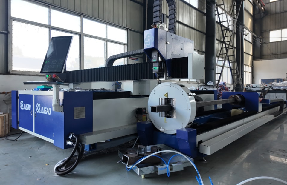
What Exactly Are Scorched Edges?
Scorched edges refer to darkened, oxidized or charred zones running alongside cutting kerfs on metal plates. This defect originates mainly from surplus heat accumulation built up throughout the laser ablation procedure.
Typical defect manifestations cover:
• Dark or black surface discoloration along cutting borders
• Severe oxidative reaction traces
• Rough, jagged cutting surfaces
• Expanded heat‑affected zone (HAZ)
• Degraded edge surface integrity
Such imperfections stand out conspicuously when processing carbon steel, stainless steel and surface‑coated metallic substrates.
The Importance of Superior Edge Finish
Sub‑par edge finish will trigger a series of manufacturing headaches:
• Extra grinding and secondary finishing workload
• Deteriorated dimensional precision of finished parts
• Obstacles for subsequent welding, spraying and surface coating workflows
• Elevated overall production expenditure
• Decreased end‑user satisfaction
To deliver premium metal fabrication outputs, obtaining bright, residue‑free cutting edges is indispensable.
Root Triggers for Blackened or Scorched Laser‑Cut Edges
Mismatched Cutting Travel Speed
Cutting travel speed exerts direct influence over heat input onto target material.
If travel speed is set too low, laser beam dwells on localized material for an unnecessarily long span, building up excessive thermal load.
Signs linked to overly‑slow cutting speed:
• Widened heat‑affected region
• Severe surface oxidation
• Heavy dark staining on cutting edges
• Abundant molten slag adhesion
Fine‑tuning travel speed to match workpiece material often yields rapid defect improvement.
Over‑High Laser Output Power
Deploying laser power beyond actual processing requirements will overheat base metal.
Although high power seems advantageous for piercing thick plates, excessive energy input will result in:
• Uncontrolled material burning
• Over‑melting along cutting kerf
• Aggravated oxidative discoloration
• Coarse, uneven cutting surfaces
Always align laser power setup with material grade and plate thickness.
Misaligned Focal Point
Focal position is decisive for final cutting performance.
When focal spot sits too high or deviates below ideal position:
• Laser energy distribution turns uneven
• Localized thermal buildup gets aggravated
• Material removal efficiency drops
• Scorch marks pop up along cutting contours
Executing focal calibration tests helps you lock in the optimum focal offset value.
Inadequate Auxiliary Gas Pressure
Auxiliary gas undertakes dual missions: blowing away molten metal melt‑drop and cooling the cutting interaction zone.
Low gas pressure will lead to:
• Incomplete clearance of molten metal debris
• Intensified oxidation reaction
• Occurrence of scorched borders
• Inferior surface texture of cutting section
Make regular checks for gas pressure regulators and delivery pipelines to maintain steady gas pressure output.
Sub‑Standard Auxiliary Gas Purity
Impure auxiliary gas poses severe negative impacts on cutting quality.
Contaminants including:
• Water vapour and moisture
• Oil vapour residues
• Fine particulate impurities
will accelerate oxidation and dark discoloration during laser processing.
Adopting high‑grade pure nitrogen or oxygen gas facilitates cleaner cutting outcomes.
Clogged Nozzle or Contaminated Protective Optics
Soiled nozzle and protective lens distort laser beam profile and beam quality.
Observable negative outcomes include:
• Uneven energy distribution across beam spot
• Diminished cutting throughput
• Local over‑heating phenomenon
• Black, scorched cutting boundaries
Scheduled inspection and cleaning serve as vital preventive countermeasures.
Step‑by‑Step Diagnostic Workflow for Scorched Cutting Defects
Step 1: Confirm Base Material Properties
First gather and validate workpiece information:
• Material alloy category
• Actual plate thickness
• Surface status and flatness
• Quality of surface protective film
Different material categories call for differentiated sets of cutting parameters.
Step 2: Double‑Check Cutting Process Parameters
Carefully go over machine operational configurations.
Verify these key items:
• Laser power magnitude
• Cutting travel speed
• Pulse frequency setting
• Focal point offset
• Auxiliary gas working pressure
Cross‑reference current setup values against JUGAO’s official recommended process parameters.
Step 3: Carry Out Nozzle Condition Inspection
Dismantle nozzle assembly and inspect for:
• Physical cracks or deformation damage
• Solidified spatter deposits
• Misalignment of nozzle bore
• Inner‑hole blockage
Replace damaged nozzle components right away once detected.
Step 4: Check All Optical Assemblies
Inspect the following optical parts:
• Protective window lens
• Focusing lens module
• Collimating lens
Any stain or contamination will degrade beam quality and cause concentrated heat accumulation.
Step 5: Run Auxiliary Gas Circuit Validation
Verify gas supply system performance:
• Gas purity grade
• Pressure output stability
• Air‑tightness of hose joints
• Functional status of pressure regulator
Sufficient and stable gas flow is critical for suppressing oxidation and scorch defects.
Step 6: Complete Test Cutting on Scrap Workpiece
After finishing parameter and hardware adjustments, perform trial cutting on leftover scrap material of identical grade.
Evaluate these indicators:
• Brightness and color of cutting edge
• Section surface smoothness
• Kerf width consistency
• Slag attachment condition
Keep iterating parameter fine‑tuning until satisfying cutting performance is achieved.
Proactive Guidelines to Avoid Scorched & Blackened Cut Edges
Keep Optical Parts Spotless
Carry out routine cleaning for optical components with designated cleaning consumables.
Well‑maintained optics guarantee:
• Stable laser beam quality
• Maximal cutting working efficiency
• Mitigated localized thermal accumulation
Keep Tabs on Auxiliary Gas Purity
Install supporting filtering units and conduct periodic gas purity monitoring.
Clean, high‑purity gas is a major contributor to bright, oxidation‑free cutting sections.
Tune Process Parameters for Every Material Variant
Do not apply one‑size‑fits‑all parameter settings for diverse workpieces.
Build dedicated parameter libraries sorted by:
• Material alloy classification
• Plate thickness range
• Original surface condition
This boosts processing consistency and shortens equipment setup duration.
Implement Periodic Preventive Servicing
Preventative maintenance checklist covers:
• Regular nozzle visual inspection
• Cyclic lens cleaning operations
• Auxiliary gas circuit examination
• Cooling loop status monitoring
• Motion axis system calibration
Consistent servicing reduces cutting defects and lowers unexpected machine downtime.
Frequently Asked Questions
What brings about black scorched edges while laser‑cutting stainless steel sheets?
Scorched edges on stainless steel are mostly triggered by improper nitrogen pressure value, deviated focal position, excessive laser power output or contaminated optical assemblies. Optimizing these items will normally resolve this defect.
Is insufficient gas pressure capable of generating black cut edges?
Absolutely yes. Low auxiliary gas pressure cannot fully expel molten metal, which allows oxidation reactions to proceed, ending up with blackened, scorched cutting boundaries.
What is the suggested inspection & cleaning frequency for nozzle and protective lens?
For continuous daily production scenarios, we advise visual inspection for nozzle and protective lens every working day; perform cleaning work whenever contamination traces are spotted.
Final Summary
Scorched and blackened cutting edges in laser cutting mainly stem from excess thermal load, ill‑matched cutting parameters, low‑grade auxiliary gas, insufficient gas pressure, wrong focal offset or polluted optical hardware. You can noticeably upgrade edge finish and production efficiency by checking these items in systematic sequence and implementing targeted adjustments.
Routine equipment maintenance, customized parameter optimization and regular component inspection are key prerequisites for acquiring bright, uniform laser cutting edges. If you need support for laser process optimization or edge‑defect troubleshooting, reach out to the JUGAO technical team for professional guidance.
Contact Us