
How to Operate a Metal Sheet Cantilever Vacuum Lifter
2026-05-28

Table of Contents
1. Performance Parameters of Metal Sheet Cantilever Vacuum Lifter
2. Handling and Installation of Cantilever Vacuum Lifter
3. Operating Steps of Cantilever Vacuum Lifter
4. Daily Maintenance of Cantilever Vacuum Lifter
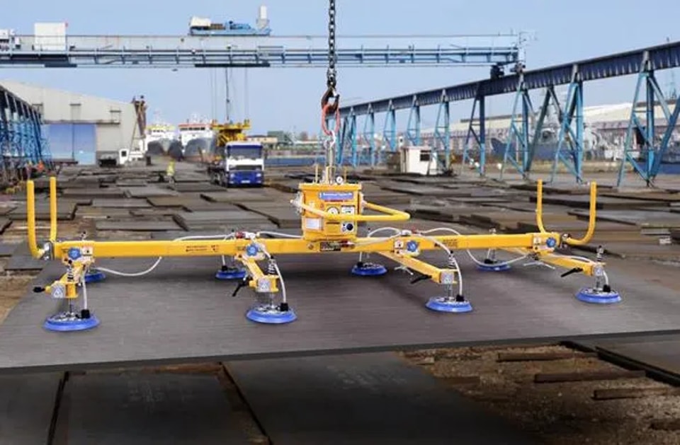
Lifting and transporting heavy metal plates has always been a difficult task in industrial operation. The metal sheet cantilever vacuum lifter can effectively solve this problem, realizing material handling work with high safety and high efficiency. This guide will elaborate on the standard operation process of the equipment in detail, helping operators master the use skills quickly and effortlessly.
The standard operating flow of the metal sheet cantilever vacuum lifter is as follows: first, firmly fit the suction cups to the surface of the metal sheet and start the vacuum system; then operate according to the instructions of the control panel to complete material lifting and position adjustment. Before formal operation, operators must verify the equipment rated load and implement all safety protection regulations. Standard operation can not only improve work efficiency but also greatly reduce the safety risk caused by improper operation.
Below we will elaborate on each module in detail to ensure safe and standardized lifting operation.
1. Performance Parameters of Metal Sheet Cantilever Vacuum Lifter
Main technical indicators of the metal sheet cantilever vacuum lifter are specified as follows:
• Working radius: 700~3200mm
• Lifting stroke: 1000mm
• Horizontal rotation angle: 0~220°
• Rated bearing capacity: 300Kg
• Applicable plate specification: 1500mm*3000mm
• Rated air supply pressure: 0.6-0.8MPa
2. Handling and Installation of Cantilever Vacuum Lifter
2.1 Safety Precautions
After the cantilever vacuum lifter is delivered to the installation site, all operation and placement work must be carried out strictly in accordance with the specifications of this manual. Operators need to carefully read and fully understand the following safety guidelines:
Hazard Warnings
1. When transferring the equipment with a crane or forklift, it is prohibited to manually support the equipment body.
2. During the handling process, personnel are not allowed to climb on the equipment or stay under the fuselage.
3. Before connecting the air supply pipeline, cut off the air source first and set up obvious warning signs at the operation site.
4. Before the equipment is started for the first time, inspect the installation status of each system to confirm all parts are installed correctly for safe use.
5. It is forbidden to absorb and lift metal plates when the vacuum pressure gauge reading is lower than 0.04MPa.
6. Any unauthorized modification of the equipment by users is not covered by the manufacturer’s warranty, and the manufacturer shall not be liable for any faults or accidents caused thereby.
General Notices
1. Overload operation is strictly prohibited; exceeding the maximum rated load will lead to equipment damage and other serious accidents.
2. Only professionally qualified personnel are allowed to operate the equipment.
3. No irrelevant personnel are permitted to enter the equipment working range to avoid personal injury accidents.
4. Do not touch the moving mechanical components during equipment operation to prevent physical injury.
2.2 Installation Environment Requirements
1. The ground horizontality of the installation site shall be controlled within ±2°.
2. The on-site foundation shall be prefabricated in strict accordance with the foundation drawing provided by JUGAO.
3. Ensure the mounting position of anchor bolts is accurate and error-free.
4. The on-site air supply pressure shall be kept between 0.6-0.8MPa with a tolerance of ±10%.
5. Reserve sufficient rotating and moving space for the rocker arm at the installation position, and set up safety isolation barriers around the rocker arm activity area.
2.3 Installation Location Layout
Arrange the installation area reasonably according to the equipment overall dimension and on-site working conditions to reserve enough operation and maintenance space.
2.4 Foundation Prefabrication Standards
The cantilever vacuum lifter needs a specially made concrete foundation, and the specific production standards are as follows:
1. Weld 6 high-strength bolts of M20×80 thread specification and 580mm length at one end, and match with another 4 bolts of the same length to form a rectangular fixing frame.
2. Customize a 2mm thick pre-positioned base plate with the overall dimension of 700mm700mm2mm.
3. During foundation pouring, keep the 2mm pre-positioned base plate flush with the ground; the exposed thread section of anchor bolts above the ground shall be 60mm, and the center of anchor bolts shall be aligned with the ∅21 positioning hole center on the base plate.
2.5 Equipment Installation Steps
Mechanical Main Body Installation
Lift the equipment column with a driving vehicle or forklift, adjust the position and height to align 8 round reserved holes at the column base with 8 embedded bolts on the foundation, place it stably and lock and fix it with M20 nuts.
Rocker Arm Installation
Lift the rocker arm by crane or forklift to keep it flush with the rocker arm fixed plate, align the thread holes and fasten and fix it with M12 screws; then connect the lifting cylinder assembly with the rocker pulley tightly.
Pneumatic Pipeline Connection
1. The rocker arm is equipped with two sets of pneumatic pipelines: the red pipeline is connected to the adsorption manipulator through a pressure reducing valve, and the blue pipeline is directly connected to the lifting cylinder.
2. Complete the vacuum pipeline connection of each suction cup group in sequence.
Equipment Commissioning
1. Adjust the air pressure value to the standard range of 0.6-0.8MPa via the pressure regulating valve; the oil-water separation cup at the bottom is equipped with an automatic drain valve, which can discharge condensed water automatically when the air pressure drops.
2. Toggle the up and down control switch on the control box to test the lifting cylinder operation. The lifting and descending speed can be adjusted by the regulating screws at the pipeline connector: the upper screw controls the rising speed, and the lower screw controls the falling speed.
3. Move the suction cup group close to the metal plate, turn on the adsorption switch, and observe the vacuum pressure gauge. If the reading can reach -0.04MPa, the pipeline is well sealed; if the value is lower than the standard, check all pipelines and switches for air leakage, and the equipment can be put into use after troubleshooting.
3. Operating Specifications of Cantilever Vacuum Lifter
3.1 Pre-operation Inspection & Preparation
1. Operators must receive professional technical training and strictly implement safety operation regulations.
2. The equipment is only allowed to transport specified metal plates, and it is forbidden to carry other sundries.
3. The single handling weight shall not exceed the rated load of 300Kg.
4. It is not allowed to suspend loads in the air unattended for a long time.
5. Regularly check all bolts and fasteners, and tighten loose parts in a timely manner.
6. Connect the air source device and adjust the air pressure to 0.6-0.8MPa.
7. Switch on the power supply and confirm the indicator light on the control handle is normally on.
8. Inspect the edge of each suction cup for scratches, cracks and other damage.
3.2 Control Panel Function Description
• Suction: Suction cup vacuum control switch. Toggle upward to start the vacuum system and adsorb metal plates.
• Release: Suction cup release switch. Toggle downward to close the vacuum system, and meanwhile blow air to the suction cup to separate it from the plate.
• Up: Lifting cylinder rising control switch. Toggle upward to drive the suction cup assembly to rise.
• Down: Lifting cylinder descending control switch. Toggle downward to drive the suction cup assembly to fall.
4. Maintenance Regulations of Cantilever Vacuum Lifter
The mechanical structure and control system of the equipment require regular maintenance and inspection. Before daily maintenance or entering the equipment working area, be sure to cut off the air source and disconnect the air supply connector.
4.1 Daily Inspection Items
1. Check the air supply pressure and air dryness, and drain the accumulated water in the pneumatic connector in time.
2. Confirm the vacuum generator operates normally without abnormal noise and failure.
4.2 Weekly Maintenance Items
1. Wipe and clean the equipment surface, and check and fasten all connecting bolts.
2. Recheck air pressure and air dryness, and inspect the working status of pressure reducing valve and drain valve.
3. Test the normal response of the negative pressure sensor.
4.3 Monthly Maintenance Items
1. Clean the dust and stains on the equipment surface to keep the fuselage clean.
2. Check whether the pneumatic connector is loose and fix it tightly.
3. Readjust the running speed of each action mechanism to keep it stable.
4. Inspect the air pipeline for aging and damage, and recheck air pressure, air dryness, pressure reducing valve and drain valve performance.
5. Fasten the bolts of all moving parts and apply an appropriate amount of lubricating oil for maintenance.
Contact Us