
Guide to using CYBELEC CybTouch 12
2026-03-27

If you're ready to begin working with the CYBELEC CybTouch 12, you've come to the right place. Mastering this intuitive touch control system is essential for anyone involved in modern press brake operations. In this guide, I’ll walk you through the fundamental steps and key features of the CybTouch 12, helping you integrate this powerful tool into your daily workflow with confidence. Whether you're just starting out or looking to fine-tune your existing skills, this article offers the practical insights needed to make the most of the CybTouch 12’s capabilities.
Introduction
Before diving into operation, it's important to note that the CybTouch 12 interface and available functions may vary slightly depending on software updates and the specific configuration of the press brake it controls. While this guide reflects the standard setup, there could be minor differences from your particular system. Rest assured, however, that any variations are typically limited and will not hinder your ability to learn and operate the controller effectively. This ensures a smooth onboarding experience, regardless of your system version.
General Navigation
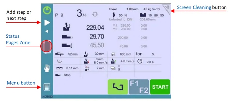
1. Menu Button
The Menu button allows you to directly select (jump to) the desired screen.
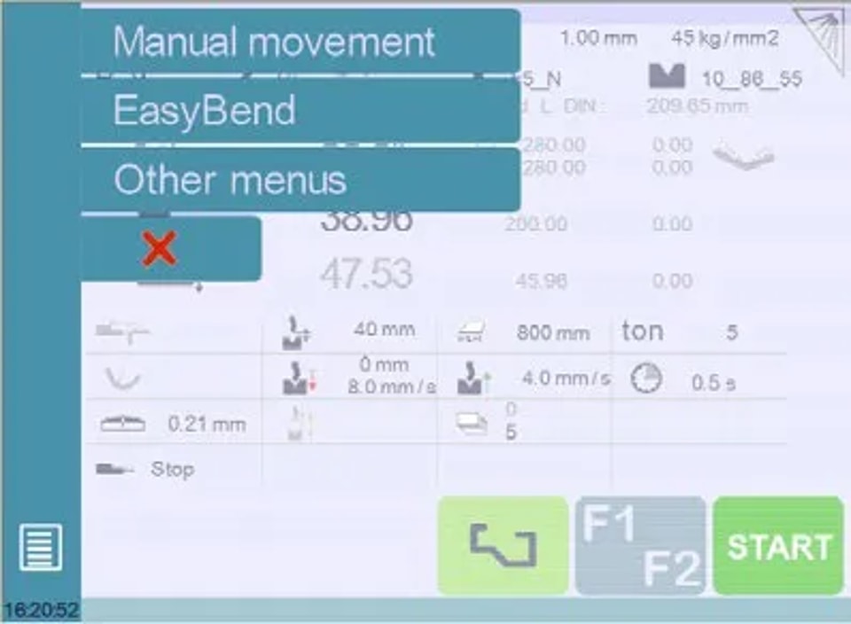
2. Status Page Zone
To get started with CYBELEC CybTouch 12, it’s important to familiarize yourself with its intuitive interface, including the Status pages zone. Briefly touching the Status pages zone gives access to the Status page. Touching this zone for more than 2 seconds will activate the Semi-Automatic mode.
3. Screen Cleaning
To clean the screen while the CybTouch is on, touch the button. Use only a damp and smooth cloth with soap or a neutral detergent.
Status Page
To get started with CYBELEC CybTouch 12, you should first explore the Status Page, which displays the status of all inputs, outputs, and axes positions of the NC. This feature is essential during setup and troubleshooting, especially for field-installed machines.
Access it easily from anywhere by pressing the Status Pages Zone, and exit by pressing the arrow on the left.
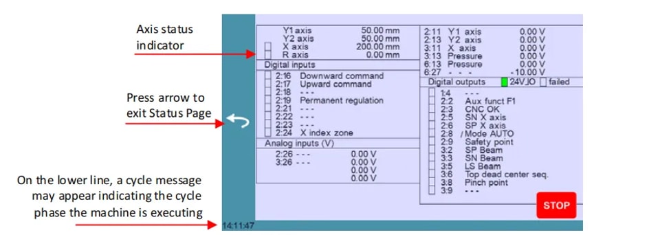
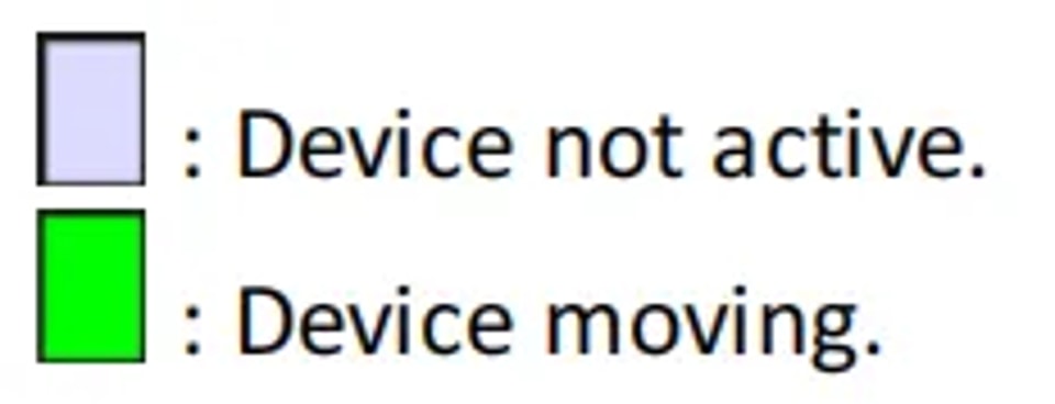
Axes have specific indicators. Their colour indicates the position of the axis relative to the tolerance.
Possible states are:
User Preferences
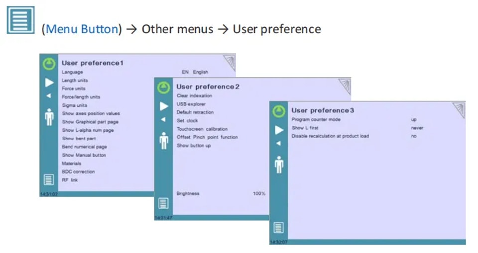
To exit the User Preference page, touch the Menu Button.
1. Language
To get started with CYBELEC CybTouch 12, a vital step is to configure your language settings to ensure optimal use. Simply touch the “Language” option on the screen to browse through the available languages:
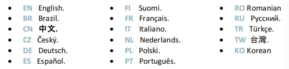
The list of available languages is subject to change and may increase over time.
2. Length Units
Choose between mm, inch, or none. If none is selected, the system defaults to millimeters.
3. Force Units
Select from ton, kN, or tons to establish the force measurement unit.
4. Force / Length Units
Configure this to ton/m, kN/m, or tons/ft to measure force per length accurately.
5. Sigma Units
Options include kg/mm², N/mm², and psi (*1000) for selecting the sigma measurement unit.
6. Show Axes Position Values
This function will display the axes positions on the Bend Numerical Page.
l When set to no, the position of axes Y1, X and R is displayed during the beam’s movements.
l When set to yes1, the positions of the axes (Y1, Y2, X and R) are displayed during their respective movements.
l When set to yes2, the positions of the axes (Y1, Y2, X and R) are constantly displayed under their respective set-point values.
7. Show Graphical Part Page
When set to yes, this button  is displayed on the Bend Numerical Page for all the graphical parts and gives access to the Graphical page.
8. Show Page L-alpha Num
When set to yes, this parameter gives access to the L-Alpha Mode. This button  is then displayed on the TouchProfile Mode page.
9. Show Bent Part
This parameter, when activated, lets the operator see the state of the part before and after the bend in the Bend Sequencing page.
10. Bend Numerical Page
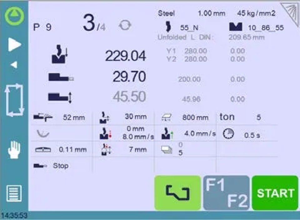
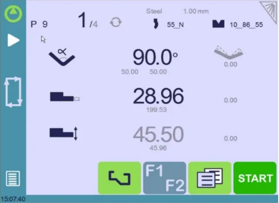
When getting started with CYBELEC CybTouch 12, customizing your display settings is essential. The system offers a parameter to choose how information is presented on the Bend Numerical Page.
By selecting “all in one” you can display all parameters related to your part or bend, a feature exclusive to CybTouch 12 due to its screen size.
When set to “More page”, this button  appears on the Bend Numerical Page, and gives access to the special page shown below.
11. Show Manual Button
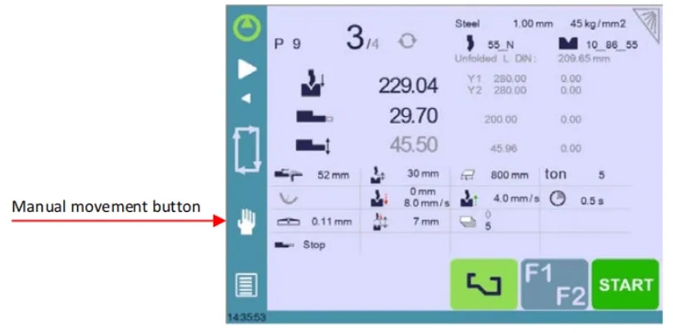
When set to yes, this parameter displays a manual button on the left side of the screen, giving direct access to the Manual Axes Movement page.
12. Materials
To get started with CYBELEC CybTouch 12 and efficiently manage your materials, you can access the Materials page where you have the flexibility to adjust default characteristics or configure new materials. Keep in mind that access to this page may depend on your machine’s parameter settings, and a level 2 password is required.
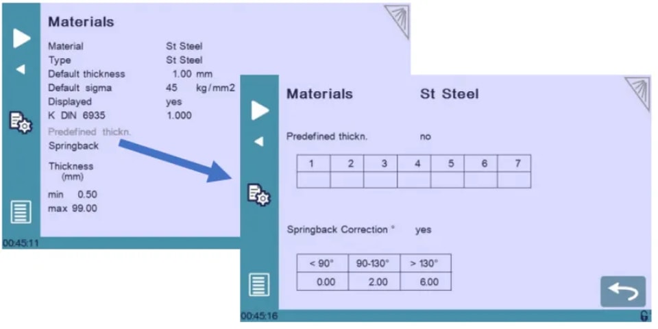
On the Materials page, you can view and modify several crucial details:
l Material: Currently selected material, such as Steel.
l Default Thickness: Automatically selected when creating a new part, based on the material.
l Default Sigma: For example, 45 for Steel, essential for calculations related to material properties.
l Displayed: Indicates the material’s availability for selection and use.
l K DIN 6935: A corrective factor for the blank length calculation as per DIN 6935 standards. Note that this value alters the thickness in the formula.
l Predefined thickn.: You can define up to seven different thicknesses for the selected material.
l Thickness Min/Max: Sets the range for acceptable material thickness.
l Springback Correction: Automatically applied during new part creation, with a customizable table based on the material.
The system provides three predefined default materials: steel, stainless steel, and aluminium. However, you can easily add more as needed. To add a new material:
l Scroll and select a non-configured material (e.g., Mater X) from the list.
l Enter the characteristics for the new material.
l Touch the name (e.g., Mater X) to bring up the keyboard and input the new material’s name.
13. Springback Correction
To get started with CYBELEC CybTouch 12, mastering springback correction is crucial for accurate bending. Each material has specific Bend Deduction Calculation (BDC), but deviations can occur. Customize the springback correction table based on experience if needed.
You can program up to three corrections based on the bending angle, with linear interpolation for intermediate values. For example, if aiming for 135° results in a 139° bend, a 4° correction can be entered in the >130° category to ensure future bends reach 135°.
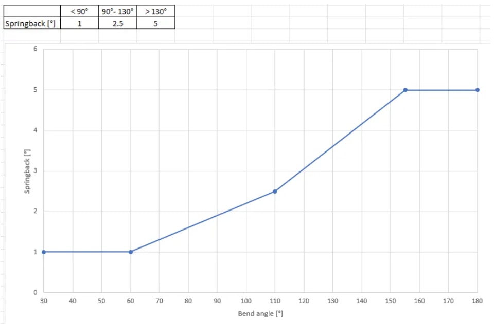
These corrections are automatically applied, so check the table for errors if bends are consistently out of tolerance.
14. BDC Correction
To get started with CYBELEC CybTouch 12, it’s essential to understand key parameters like the Bottom Dead Centre (BDC) correction. This adjustment is continuously applied, though not shown on the correction page. If you notice unexpected results, check this parameter’s value. Should your bends fall out of tolerance, consult a technician to review the machine’s beam index value.
15. RFLink
When you get started with CYBELEC CybTouch 12, you’ll discover its ability to communicate with a laptop using Cybelec’s RFLink dongle. This feature, initially off by default and reset with each start-up, is primarily used by technicians during machine initialization.
16. Clear Indexation
When activated, this function clears the index and the machine will search for them, as it does when turning the power on, allowing the operator to re-index its machine without turning it off.
17. USB Explorer
When this parameter is set to yes, it is possible to browse the USB key from the USB Transfer page to access specific folders. (see USB Transfer)
When set to no, all data (tools, part) will be in a folder called dataCybT at the root of the USB key when exporting files. If you wish to import files, make sure the data is in this same folder.
18. Default Retraction
When getting started with CYBELEC CybTouch 12, it’s important to understand the back-gauge retraction function. This parameter sets the default value in the Extra Bending Parameters, triggered when retraction is needed.
In Graphical Mode, the system automatically calculates this, but you can manually adjust it for precise control in your operations.
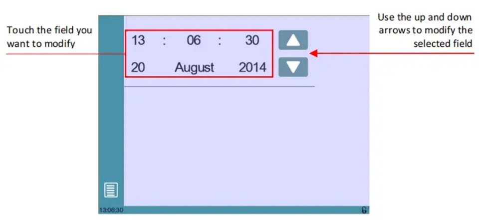
19. Set Clock
Allows the user to set the time and date on the CybTouch.
20. Offset Pinch Point Function
When this parameter is set to yes, the Offset Pinch Point function is available in the Extra Bending Parameters.
21. Brightness xx% Eco xx%
Here the brightness of the screen for normal mode and Eco mode can be defined:
l Touch the mode for which you want to modify the brightness.
l Use the  buttons to set the brightness.
22. Program Counter Mode
You can set it to count “up” to your desired number or “down” to zero. The cycle will stop once the total is reached, and the counter’s value is automatically saved when the system is shut down.
23. Show L First
To get started with CYBELEC CybTouch 12, you need to configure the back gauge data entry mode. Set it to “yes” to display the flange length for external dimensions, or “no” to show the back gauge position in millimeters for internal dimensions.
Choosing “never” disconnects the position from the bending angle changes, which is the default setting. A full reset will return settings to default. Note, this mode isn’t available for graphical parts.
24. Disable Recalculation at Product Load
When getting started with CYBELEC CybTouch 12, it’s essential to manage the recalculation of axes position values when a part is loaded, especially if tool dimensions or back gauge settings have changed. By default, this recalculation is off, but using corrections for program fine-tuning is recommended.
25. Indexation Aids
When you get started with CYBELEC CybTouch 12, enabling indexation aids can be crucial. This feature displays a pop-up for errors during beam indexation, halting the cycle to prevent endless upward movement, and guides users to manually lower the beam if needed, ensuring smooth operation.
26. Beam stops during retraction
When enabled, the beam stops at the pinch point during back gauge retraction. When disabled, the beam slows down slightly but continues bending as the back gauge retracts.
Manual Axes Movement
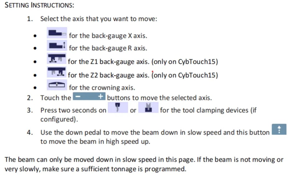
In the course of setting up a machine, it is sometimes necessary to be able to move the axes manually, for example when changing the tooling. This can be done on this page.
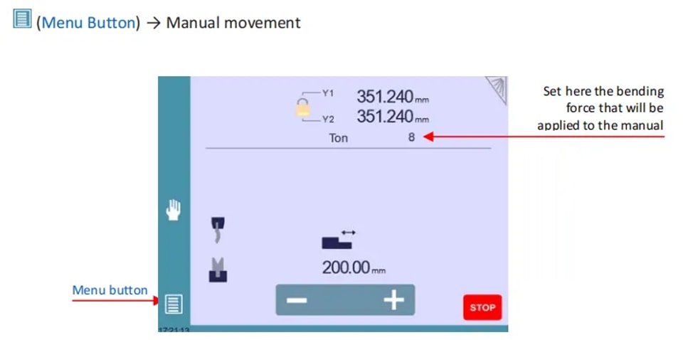
Desynchronized Beam
To get started with CYBELEC CybTouch 12, unlock the padlock to select and move Y1 or Y2 separately at low speed. This feature allows for easy realignment of an unsynchronized beam to the table. Once unlocked, the highest Y is selected automatically, letting you lower it with the down pedal to straighten the beam.
Service Page
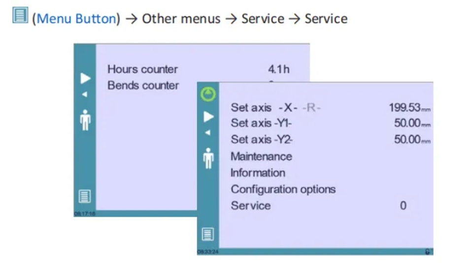
1. Set Axis
Allows the operator to manually adjust the position of the back gauge (axes X and R) and the beam (axes Y1 and Y2).
2. Maintenance
The Maintenance page displays the hardware status of the CybTouch and lets the operator perform different maintenance actions.
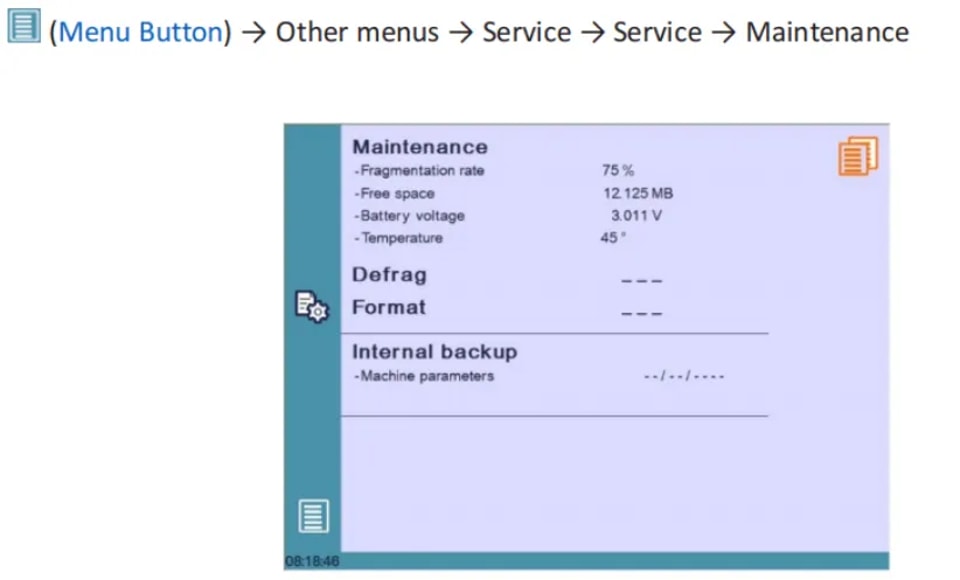
All the following actions require codes and should only be performed by technicians or upon request of a technician.
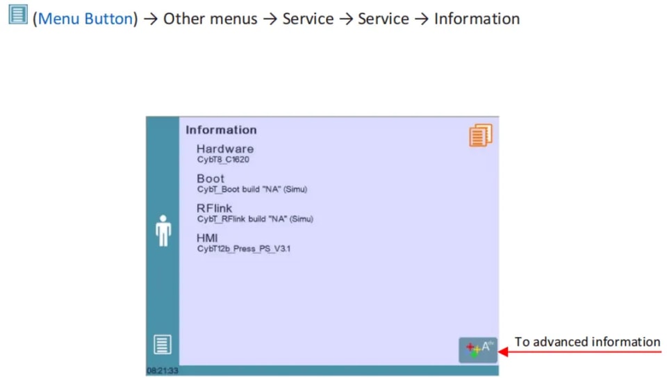
3. Information
The Information page displays the names and versions of the software installed on the CybTouch. Pressing the Advanced button shows more detailed information.
4. Configuration Options
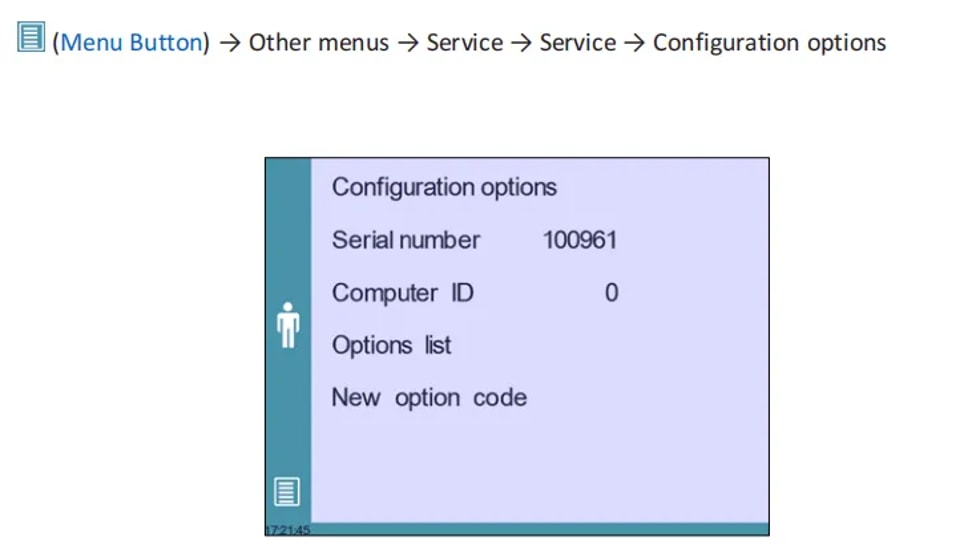
l Serial Number
Essential for setup, the serial number ties to the machine’s options. Changing it may result in losing installed options.
l Computer ID
Unique to each unit, it ensures proper machine identification along with the serial number.
l Option List
A yellow pop-up displays all installed options, helping you track the available functionalities.
l New Option Code
Enter a code in the format ABC-DEF-GHI-JKLM to add new options. Consult a technician or manufacturer for assistance.
USB Transfer
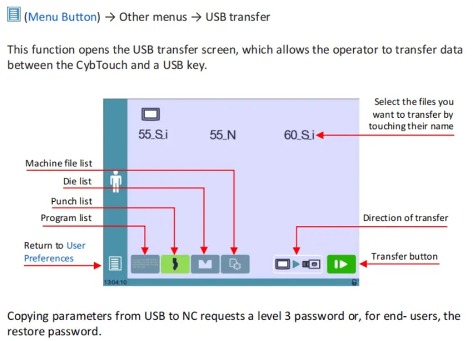
To ensure smooth file transfers with CYBELEC CybTouch 12, keep these precautions in mind:
l USB Compatibility: Use “Memory stick” type USBs. While USB 3.0 keys that are USB 2.0 compatible usually work, results can vary. Avoid CDs and external HDDs.
l Troubleshooting: If a USB key is incompatible, switch to another one.
Quick Transfer Tips:
1. Dedicated USB Key: Use a USB dedicated to CybTouch file transfers.
2. Limit Files: Fewer files speed up the transfer.
3. Character Limit: Keep file paths under 255 characters.
By following these steps, you can effectively get started with CYBELEC CybTouch 12.
Conclusion
A proper setup of the CYBELEC CybTouch 12 is essential to unlocking the full potential of your press brake. By carefully following the recommended installation and configuration steps, you ensure smooth and reliable machine operation—reducing the risk of errors, minimizing downtime, and laying the foundation for consistent performance. Regular maintenance and adherence to operational best practices will further extend the lifespan of your system and help sustain long-term productivity.
Understanding the system’s capabilities and any version-specific nuances allows you to operate the CybTouch 12 with greater confidence and efficiency, minimizing disruption while optimizing your bending processes.
If you have questions or need further assistance, our support team is ready to help. Be sure to explore our full library of documentation for additional insights and detailed guidance on maximizing your machine’s performance. Whether you're fine-tuning settings or troubleshooting, we're here to support you every step of the way.
Contact Us