- tel:+86-13222111178
- email:info@ntjugao.com


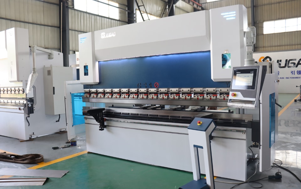
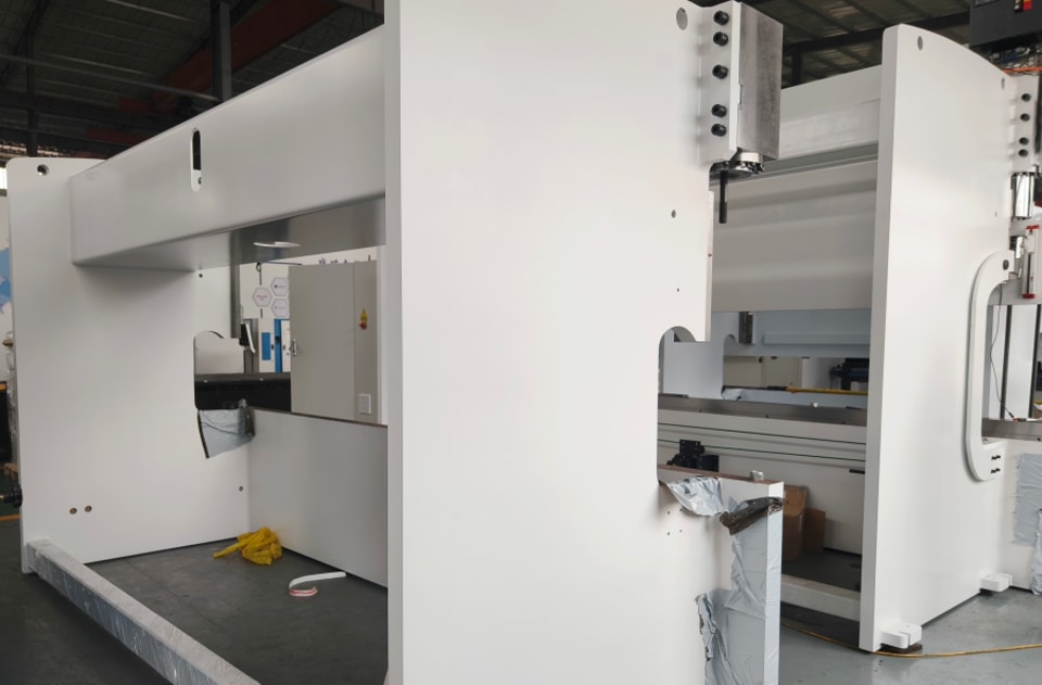
Main structure of the Press Brake
Main structure of the Press Brake

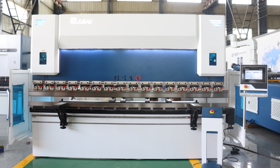
1.Introduction to mechanical structure:
The hydraulic bending machine is mainly composed of a bed, a slider, a back gauge, a hydraulic system, a mold, a support rack, a safety protection device, an electrical system, etc.
2.Mechanical connection
(1) The upper slider is connected to the piston rod in the two cylinder assemblies and supported on the left and right wall panels through the bottom plate of the cylinder. There are left and right guide rails to provide guidance for the slider to move up and down. There is a spherical pad at the connection between the piston rod and the slider to ensure that the force on the beam is reasonably distributed and the piston rod is in good alignment.
(2) According to the different forms of the main machine, the lower beam (workbench) of the bending machine produced according to customer requirements has two forms. One is a single-beam type fixed with screws; the other is a three-beam type with a compensation cylinder. Adjustable pads are provided on both sides to correct the pads and the body fitting surface, and the correction accuracy can be adjusted.
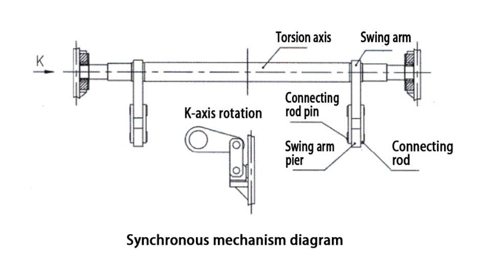
(3) In order to ensure the synchronous operation of the left and right cylinders, the machine tool adopts a synchronous torsion axis swing arm and connecting rod.
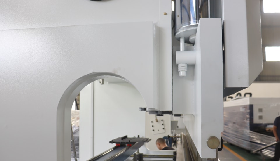
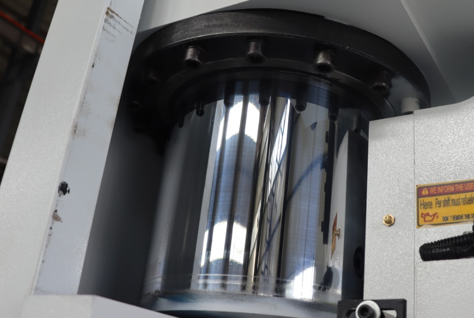
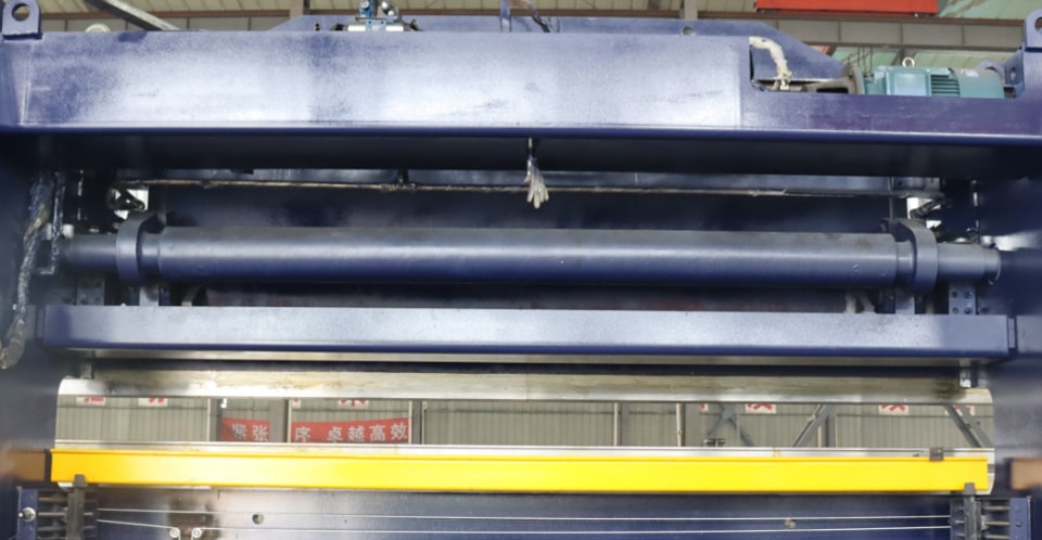
3.Slider part
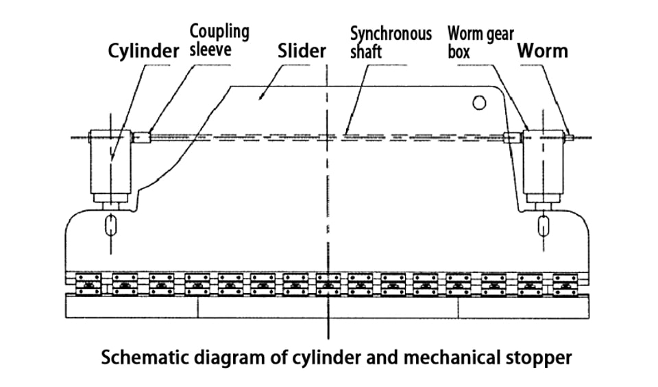
The slider part consists of a slider, a cylinder and a mechanical stopper fine-tuning structure. The left and right cylinders are fixed on the frame, and the piston (rod) drives the slider up and down through hydraulic pressure.
The mechanical stopper is placed inside the two cylinders, with a compact structure and synchronous adjustment on both sides. The schematic diagram is as follows. When the slider (upper) is not equal on the left and right, stop the slider at the top dead center, remove the positioning pin on the coupling sleeve, turn the worm on either side of the worm gear box on the left and right cylinders (forward or reverse), and then press the slider to the bottom dead center, measure and adjust (repeat the above operation) until the slider (upper mold) is equal on the left and right, and finally position and install it on the coupling sleeve.
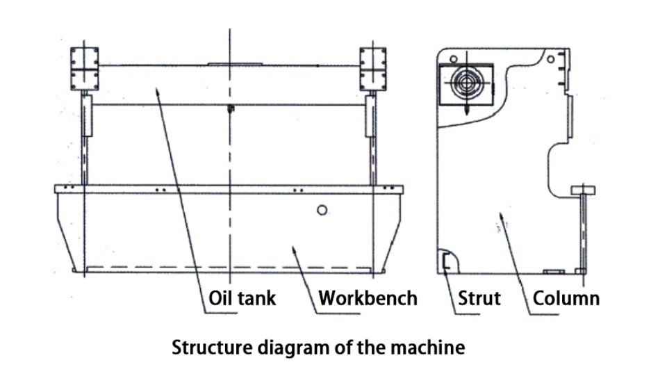
4.Frame
The frame is welded into an integral frame by left and right columns, oil tanks, and support blocks, and the workbench is fastened to the lower part of the left and right columns.
5.Synchronous mechanism
The mechanical forced synchronous mechanism composed of a torsion shaft and a swing arm has a simple structure, stable performance and high synchronization accuracy.
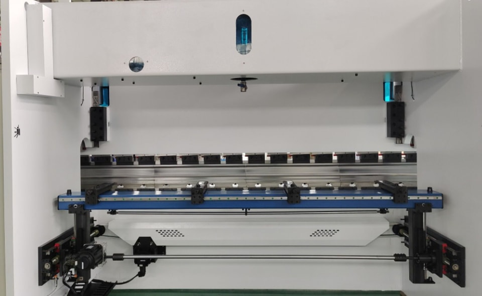
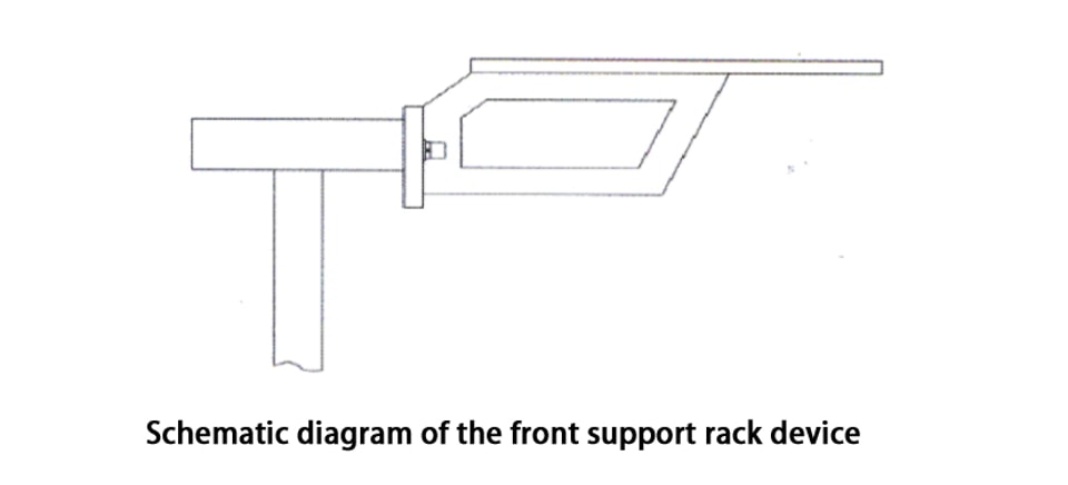
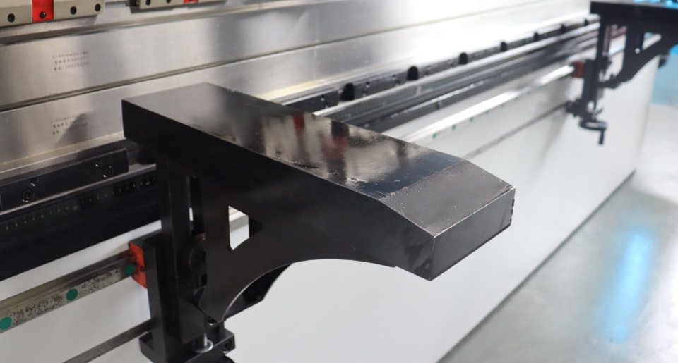
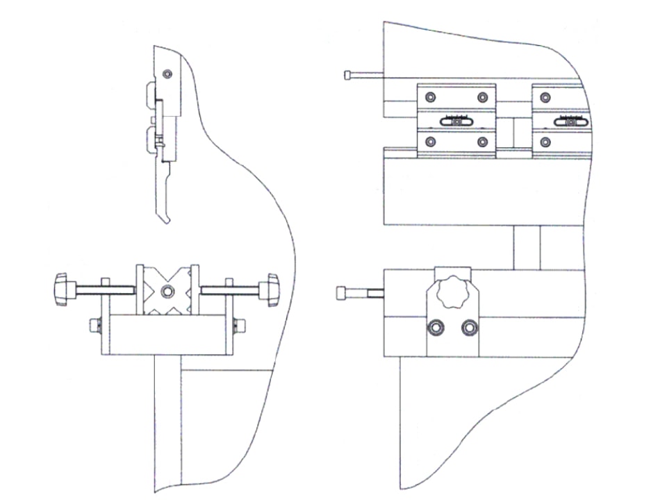
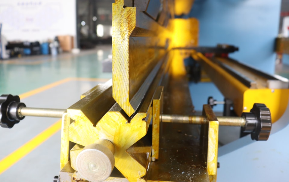
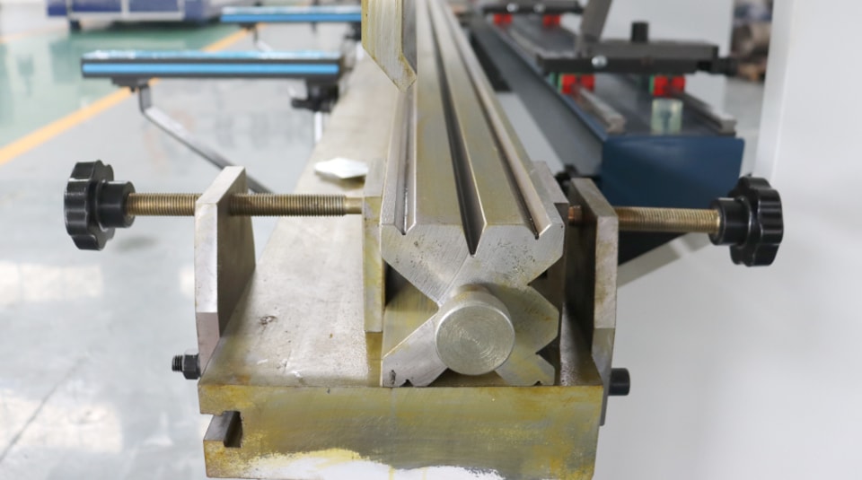
6.Front support rack device
The front support device is used to support and hold the workpiece.
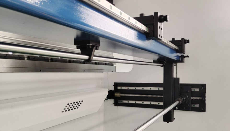
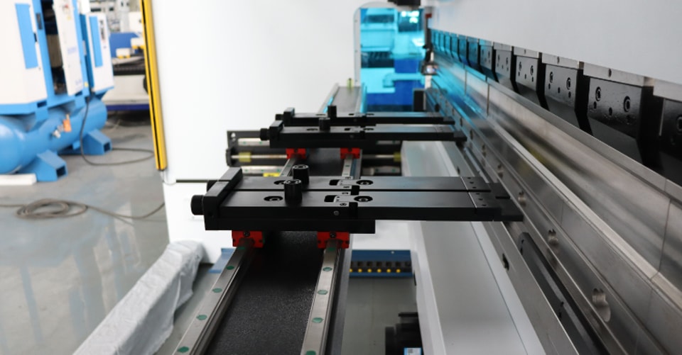
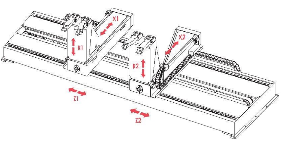
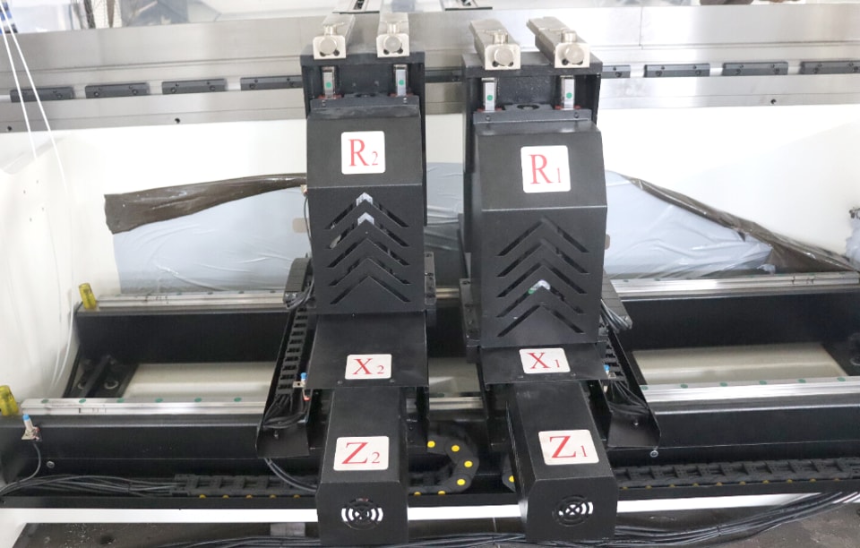
7.Back gauge
The back gauge is a valuable component of the machine tool and plays an important role in the actual bending work. The following is some description of the back gauge: It is operated by the button on the operation panel to make the motor drive the back gauge frame to move forward and backward.
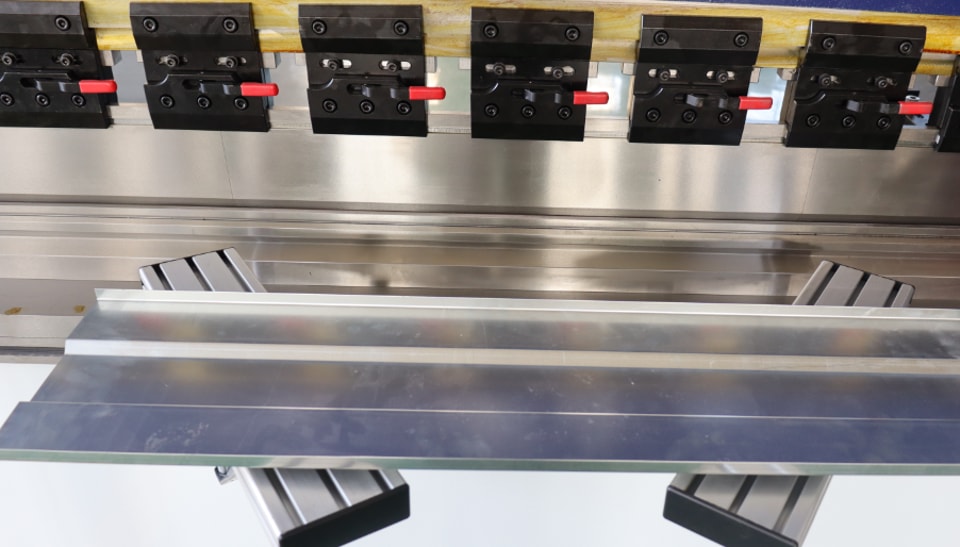
8.Press Brake Die
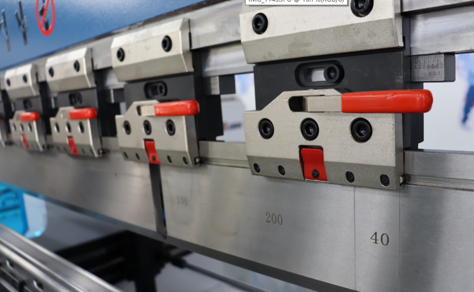
(1)The upper mold is installed on the slide and fixed with a connecting plate and a pressure plate. The upper mold is equipped with a fine-tuning mechanism, which moves left and right obliquely and is used for the upper and lower compensation fine-tuning of the upper mold to ensure the accuracy of the bending workpiece.
The lower mold is installed on the workbench. The rotating handle can push the lower mold to move forward and backward to align the center of the upper mold blade.
(2) Mold installation
- The installation and removal of the mold should be completed by trained and authorized professionals and strictly follow the requirements of the electrical specifications.
- Adjust the slider to the appropriate top dead center position according to the selected mold height.
- When installing the mold, the oil pump should be turned off and the machine tool should not be started.
- Remove impurities, burrs and flash from the mold and the mold installation surface.
- Install the upper mold first, then the lower mold.
- After the mold is installed, pay attention to tightening the screws.
- After the machine tool is installed, start the oil pump to move the slider downward and control it at the required appropriate position. Check whether the upper and lower molds are aligned, that is, whether the gaps on both sides of the upper mold are equal in the V groove. If not, adjust the lower mold and fix the lower mold to return the machine tool to the top dead center. (Note: Keep the gap between the upper and lower molds larger than the thickness of the plate to be folded).
- Adjust the inclined wedge so that the bottom surface of the upper mold can be adjusted to obtain the minimum bending angle error over the entire bending length. In order to obtain a good bending effect, the inclined wedge can be readjusted according to the actual bending result of the test piece. If the actual bending angle at this point is too large during adjustment, the bottom surface of the mold at this point should be adjusted downward, that is, loosen the clamping screw and move the wedge to the left. After adjustment, tighten the screw. Otherwise, adjust the bottom surface of the mold upward, that is, move the wedge to the right.
(3) Matters to be noted when using the mold:
- Check the fixing screws of the mold regularly
- Be careful when replacing the mold, and place the mold gently on the mold frame next to the machine tool to avoid damage.
- Each mold has its maximum load capacity, and it is not allowed to be overloaded and bent.
- When not in use for a long time or stopped, the upper mold should be lowered into the V-groove of the lower mold, in contact with the lower mold or on a flat plate.
- When the mold is not in use, in order to protect the mold blade, the mold can be placed on a wooden board or rubber skin, and the mold surface can be greased.
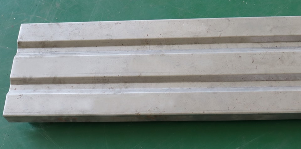
(4) The following workpieces can be folded
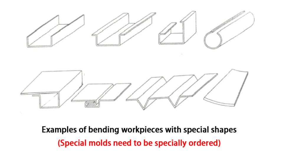
Contact Us