
Can a CNC Tube Bender Make Your Part? Check Radius, Straight Length and Tool Clearance
2026-09-29

Can a CNC Tube Bender Make Your Part?
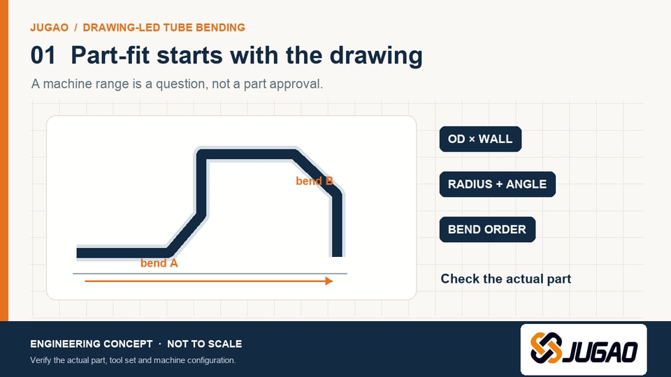
Check radius, straight length and tool clearance before you buy.The largest tube diameter and a published radius table cannot replace a check against your actual part. Give the supplier the material, OD and wall, radius definition, every bend angle, tangent-to-tangent straight, rotation and bend sequence, end grip and surrounding space. Ask for confirmation against the quoted machine and tool package, then validate a representative sample with an agreed drawing and measurement method. Buy the verified machine–tool–part combination, not one capacity number.
Radius words are not interchangeable
Centerline radius (CLR) follows the center of the tube through a bend. Inside radius refers to the inner wall; outside radius to the outer wall. Confirm which reference the drawing uses before matching it to a machine or die specification.
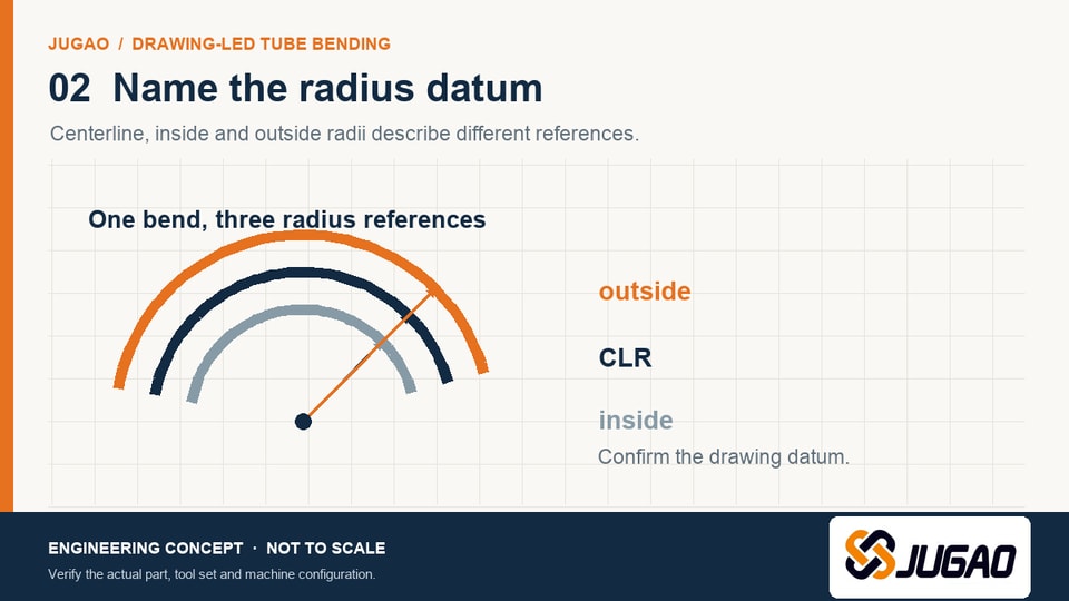
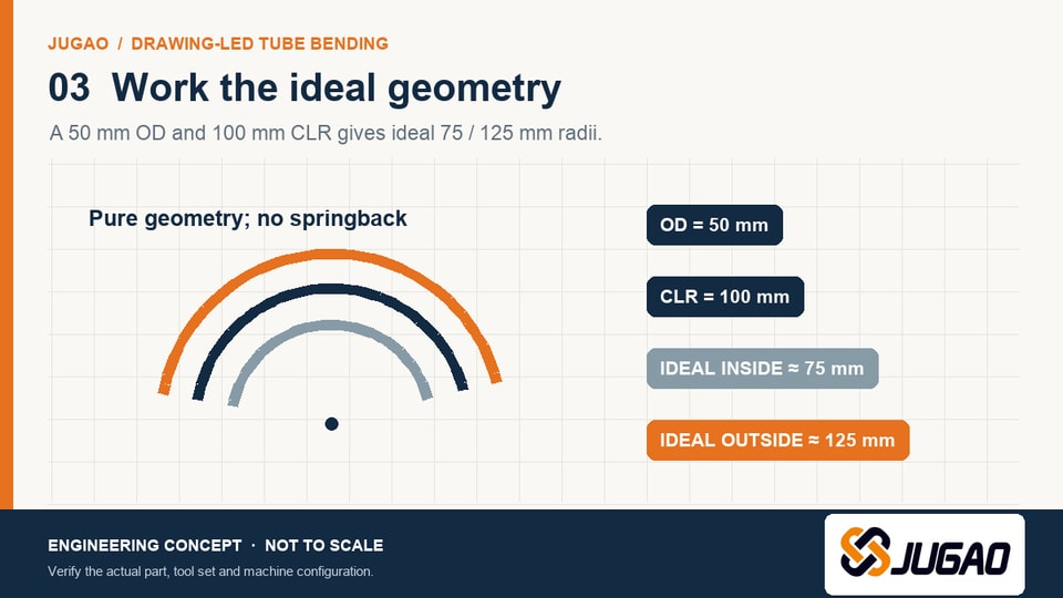
For an ideal circular bend with unchanged tube cross-section, inside radius is approximately CLR − OD/2 and outside radius CLR + OD/2. With OD 50 mm and CLR 100 mm, the ideal values are 75 mm and 125 mm. This is geometry only, not a trial result or finished-part promise; springback, ovality, wall change, wrinkles and tool contact can change the measured part.
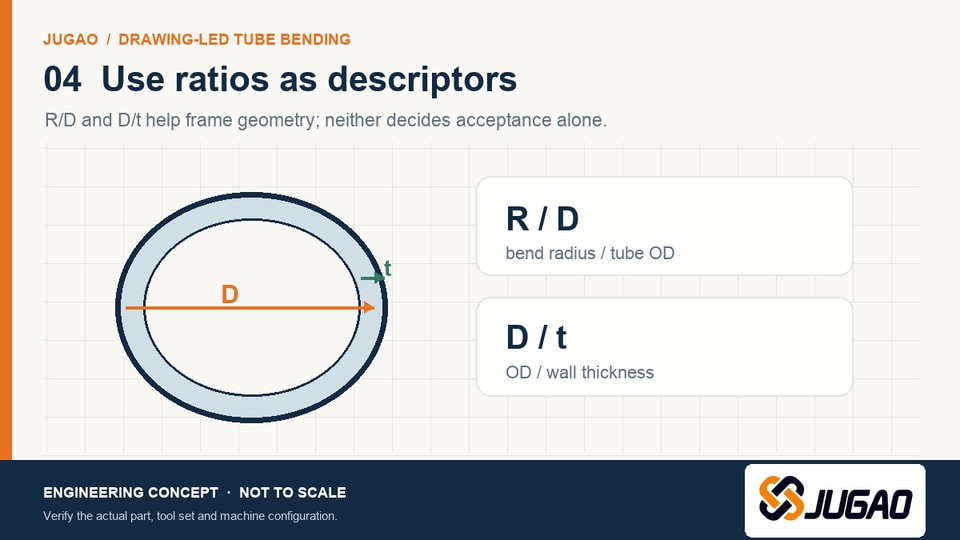
The ratios R/D (centerline radius ÷ tube OD) and D/t (OD ÷ wall thickness) describe bend tightness and relative wall thickness. They are useful screening terms, not universal pass/fail rules. Material, tube condition, seam, tolerances, lubrication, tools and inspection requirements remain part specific.
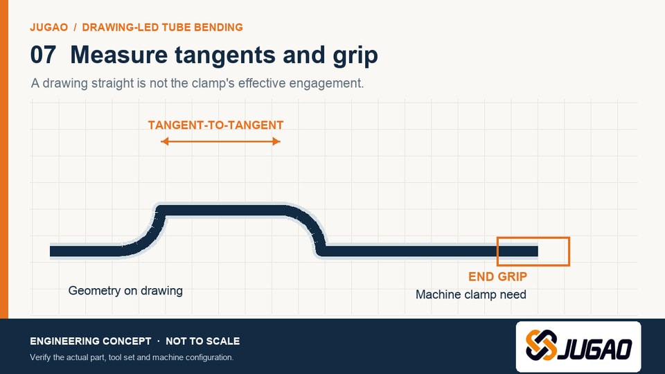
Record each tangent-to-tangent straight between bends and the separate end allowance available to a clamp or collet. A geometric straight on the drawing is not automatically the effective grip length needed by a chosen tool during a particular bend order. Ask for the shortest segment to be checked on the quoted machine with its actual clamp and tools.
Use ER-63 CNC fields as questions
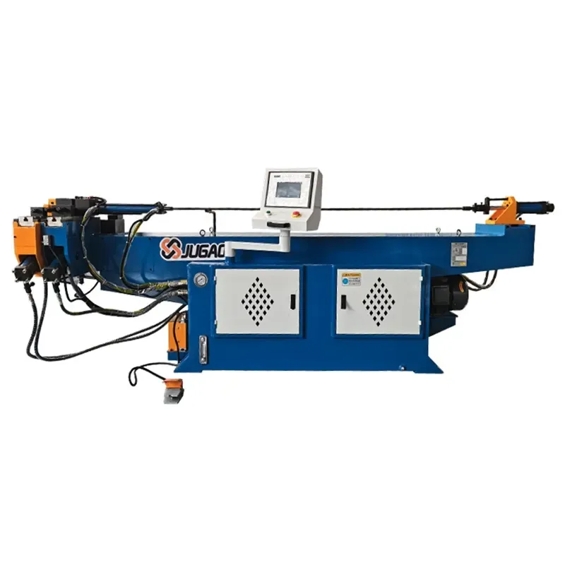
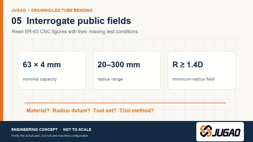
The JUGAO ER-63 CNC product page lists 63 × 4 mm nominal maximum capacity, a 20–300 mm radius range and R ≥ 1.4D. The page does not tie these fields to a complete material, tube condition, radius reference, tool set or sample method. Use them to frame questions for the supplier; do not treat them as an order-level fit guarantee.
| Published field | Useful first question | Unknown condition to confirm |
|---|---|---|
| 63 × 4 mm | What OD × wall and material was this capacity defined for? | Material, strength, tube condition, weld and target geometry. |
| 20–300 mm | Which radius definition applies? | CLR, inside or die radius; test tube and tools. |
| R ≥ 1.4D | How is this field interpreted for our part? | OD, wall, material and relationship to the radius range. |
| 4000 mm / 3000 mm | What are the reference points and usable lengths? | Mandrel-area effective length versus feed stroke, clamp and tail allowance. |
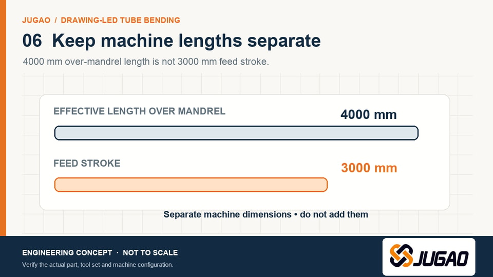
The same page separately lists 4000 mm effective length over mandrel and 3000 mm feed stroke. They may use different mechanical reference points. Do not add, interchange or use either as the maximum finished-part length without reviewing grip, tail, tools and bend sequence. The page also has unclear units in its angle and pressure fields, which this guide does not repeat as usable claims.
Clearance is a sequence, not a still image
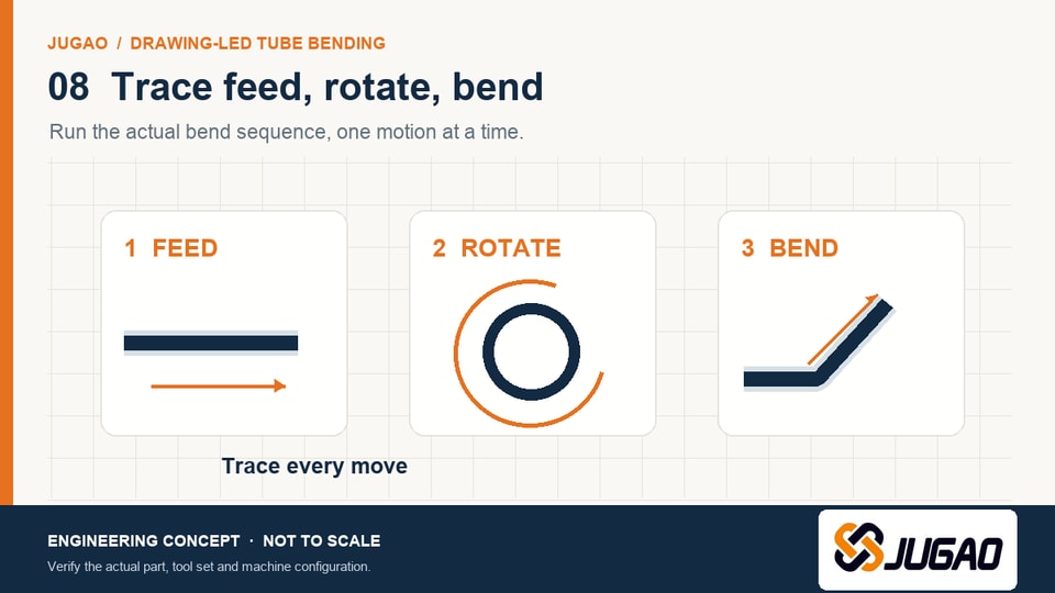
Break the proposed program into feed, rotation around the tube axis and bend for every move. Record bend angle and plane, feed distance, shortest tangent, possible regrips and the final tail position. A finished CAD shape that fits in a static box may still be impossible to make in that order.
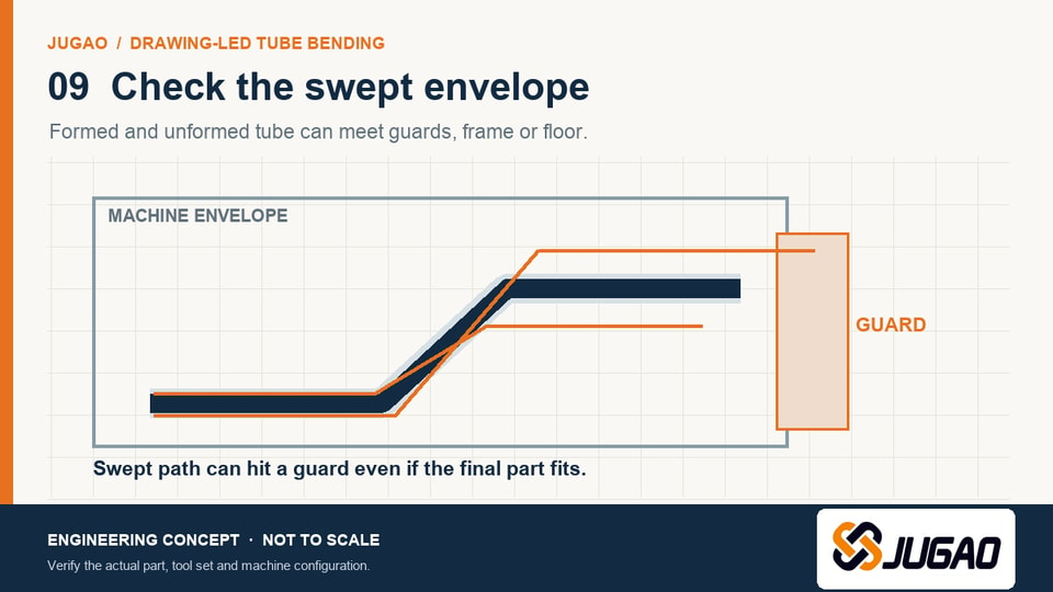
At each step, check the swept space of already formed tube and remaining straight stock against the clamp, bending arm, mandrel rod, frame, guarding, floor, rack, robot and nearby equipment. Include loading access and the last bends, when tail length and rotation space may be most restrictive.
Tool names describe jobs, not coverage
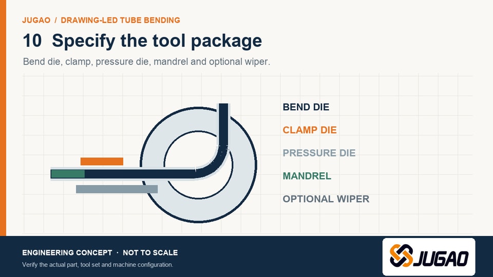
In rotary draw bending, the bend die guides the bend path, the clamp die grips a tangent section, and the pressure die supports the straight side. A mandrel may support the inner wall, while an optional wiper die can help control inner-arc wrinkles. Ask which tool numbers, sizes, surface protection and insertion or withdrawal motions are included for your part.
Tool contact and alignment depend on material, OD, wall, CLR, surface and bend order. A peer-reviewed study of machine-axis stiffness and wrinkles shows how pressure-die position and axis movement can affect wrinkle formation within its defined setup. Its 0.2 mm experimental step is not a universal setting for a JUGAO machine.

Experimental numbers are not your order
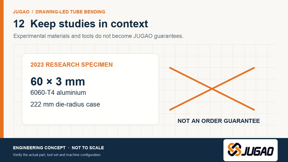
Another peer-reviewed comparison of compression and rotary draw bending used 60 × 3 mm 6060-T4 aluminium tubes and a 222 mm tooling radius in its reported experiments. It helps explain springback and cross-section change under those conditions. Neither its results nor the other paper's tool adjustments can be promoted as JUGAO ovality, thinning, angle or tolerance guarantees for a different material or machine.
Send a drawing that can get a clear answer
Send the same revision of the 2D drawing and 3D model to every supplier. Include material grade and condition, OD × wall and tolerances, weld position, radius definition for each bend, angles and planes, tangent lengths, end grip, quality limits and surrounding cell constraints. Ask the supplier to return a marked-up drawing with assumptions, proposed machine and tool numbers, bend order and unresolved risks.
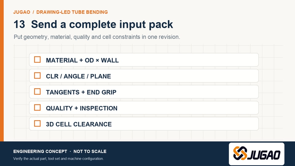
- Material, condition, OD × wall, tolerances and weld
- CLR, inside or die radius for every bend
- Angle, plane, rotation, order and regrip points
- Tangent-to-tangent lengths and end grip
- Ovality, thinning, wrinkle, crack and surface needs
- 3D cell, guards, loading and tail-stock limits
Agree the controlling drawing revision, representative material, sample quantity, where and how dimensions will be measured, and the allowable values before a trial. Record angle after unloading, radius reference, tangent lengths, section shape, wall and surface condition, and any assembly-gauge result. Limits come from the part drawing, applicable standard or a written agreement; this guide sets no universal tolerance.
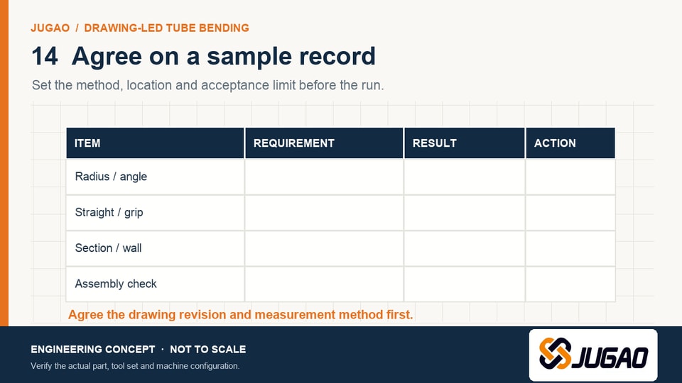
| Item | Requirement / tolerance | Measured result | Pass / action |
|---|---|---|---|
| Radius definition and value | To agree | — | — |
| Unloaded bend angle | To agree | — | — |
| Tangent-to-tangent straight | To agree | — | — |
| Section shape / wall / surface | To agree | — | — |
| Assembly or gauge check | To agree | — | — |
Questions to settle before the PO
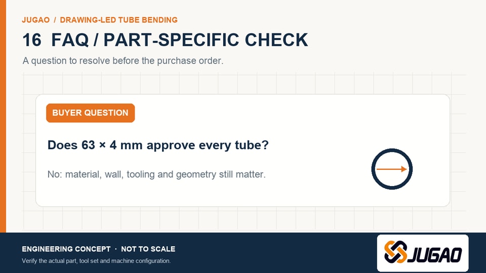
Does “63 × 4 mm” approve any tube of that size?
No. Ask how material, strength, tube condition, weld, tooling and target geometry affect your part.
Are 20–300 mm and R ≥ 1.4D interchangeable?
No shared test conditions are published. Ask how both fields apply to your OD, material and tool set.

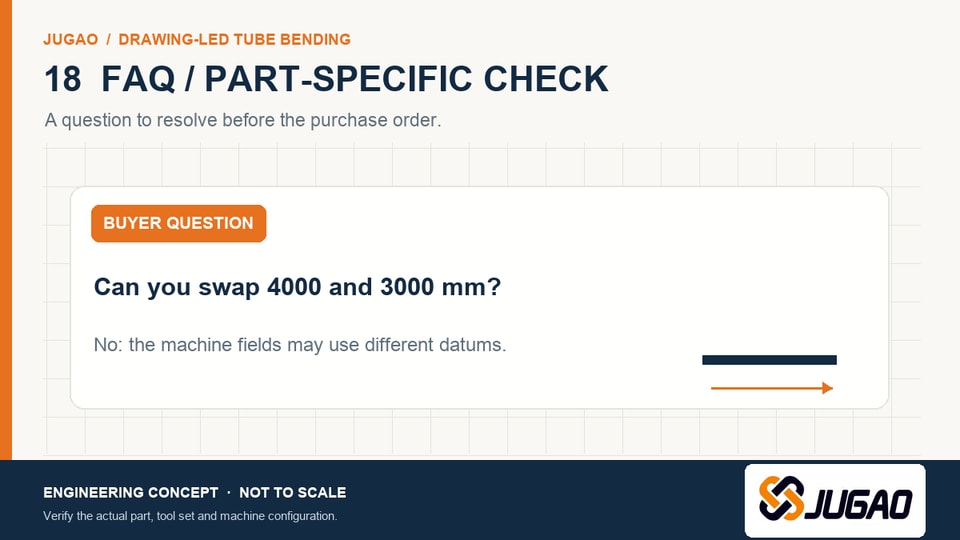
Can 4000 mm replace the 3000 mm feed stroke?
No. They are separate machine fields and may use different reference points.
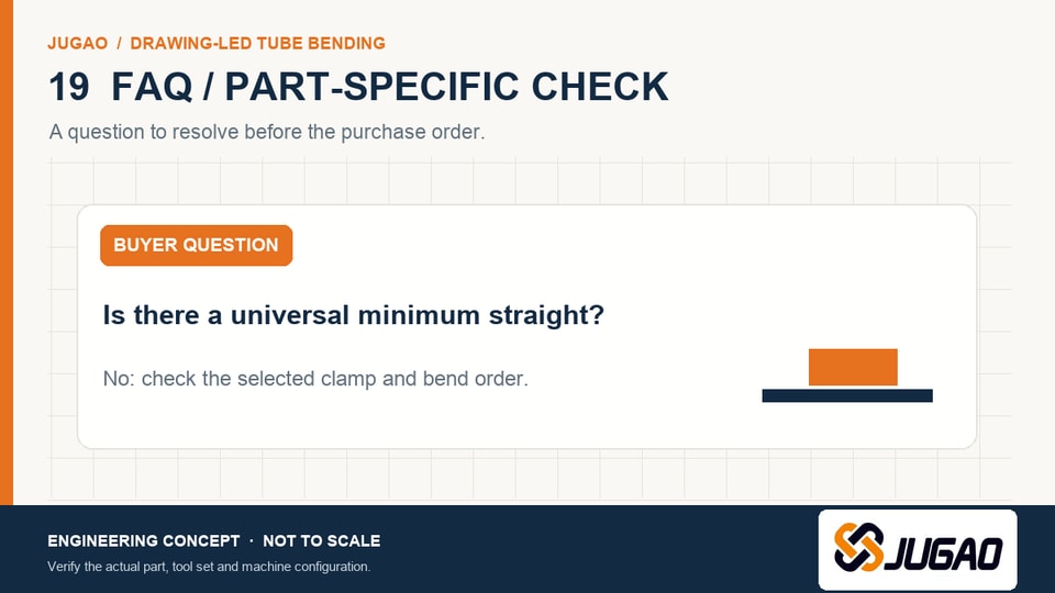
What is the minimum straight between bends?
There is no universal multiplier. Check the actual machine, clamp, tools and bend sequence.
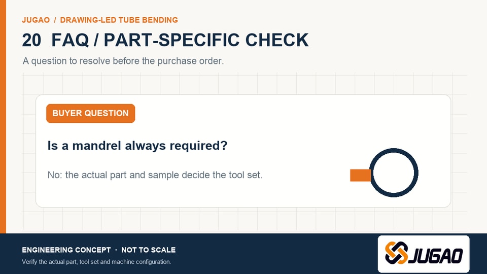
Do I always need a mandrel or wiper?
No. Confirm the need against material, geometry, surface limits and a representative sample.
Can a paper prove my machine tolerance?
No. A buyer order needs a written acceptance plan and representative sample.

Ask for a drawing-based review
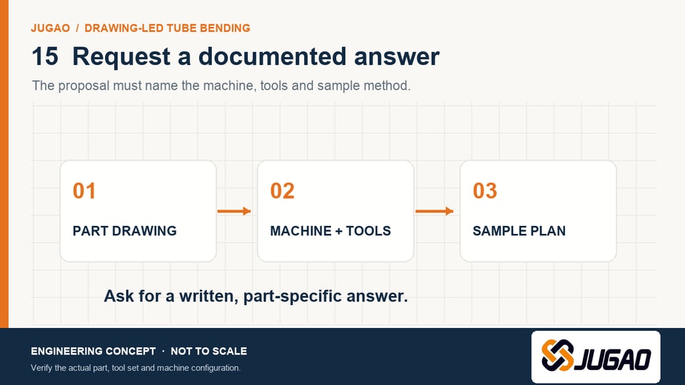
Send the drawing revision, material, OD × wall, radius definitions, bend sequence, shortest tangent, grip allowance and acceptance requirements. Ask JUGAO to identify the proposed machine, tool package and sample method. Review the ER-63 CNC product page for its published fields, then contact JUGAO with your part package.
Sources and scope
- JUGAO ER-63 CNC hydraulic pipe bending machine, public product fields checked 29 September 2026.
- Borchmann, Heftrich & Engel, 2020, machine-axis stiffness and wrinkles in rotary draw bending; study setup only.
- Tronvoll, Ma & Welo, 2023, compression versus rotary draw bending; 60 × 3 mm 6060-T4 aluminium and 222 mm tooling case.
Contact Us