 Get a quote
Resources
Relationship between sheet metal bending radius and plate thickness
Sheet metal bending radius is a value required in sheet metal drawings, and it is difficult to determine how large it is in actual processing. In fact, this sheet metal bending radius is related to material thickness, bending machine pressure, and bending die slot width. What is the specific relationship? Let's study it today:
According to experience in actual sheet metal processing: When the plate thickness is generally not more than 6mm, the inner radius of the sheet metal bending can be directly used as the radius when bending.
When the plate thickness is greater than 6mm and less than 12mm, the inner bending radius of the plate is generally 1.25 to 1.5 times the plate thickness. When the plate thickness is not less than 12mm, the inner bending radius of the plate is generally 2 to 3 times the plate thickness.
When the bending radius is R=0.5, the general sheet metal thickness T is equal to 0.5mm. If a radius size greater than or less than the plate thickness is required, a special mold is required for processing.
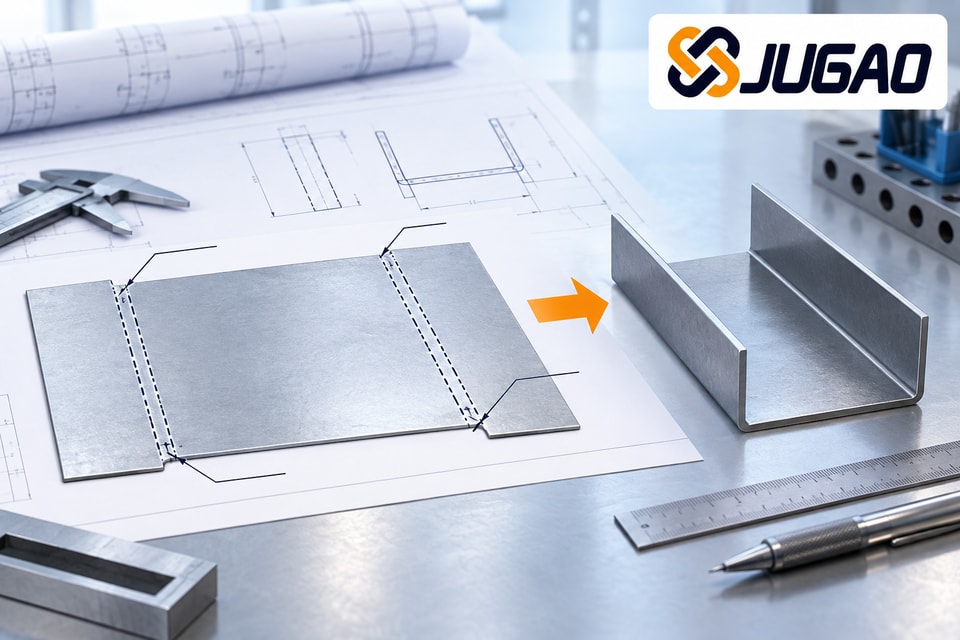
When the sheet metal drawing requires the sheet metal to be bent 90°, and the bending radius is particularly small, the sheet metal should be grooved first and then bent. Special upper and lower dies of the bending machine mold can also be processed.
The bending radius of the sheet metal is related to the size of the lower die groove of the bending mold.
Through a large number of experiments in sheet metal processing, it is found that the lower die width of the bending mold has a certain relationship with the size of the bending radius. For example: 1.0mm sheet metal is bent with an 8mm groove width, so the bending radius pressed out is R1 in the ideal state.
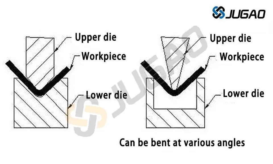
If a 20mm groove width is used for bending, since the upper die moves downward during bending, the depth of the stretched sheet metal reaches a certain angle. Then we know that the area of the 20mm wide groove is larger than that of the 8mm wide groove. When bending with a 20mm width, the stretching area also increases and the R angle also increases.
Therefore, when there is a requirement for the bending radius of the sheet metal and it does not damage the bending machine mold, we try to use a narrow groove for bending. Under normal circumstances, it is recommended to operate according to the standard ratio of plate thickness to slot width of 1:8. The minimum ratio cannot be less than 1:6 for plate thickness to slot width. Sheet metal bending can be appropriately smaller, and cannot be less than 1:4 for plate thickness to slot width. Suggestion: If strength permits, it is preferred to use the method of planing grooves first and then bending to make a small bending radius of sheet metal.
The bending radius of sheet metal processing depends on the material thickness and the width of the bending slot. The simple, convenient and rough method is:
When the plate thickness is not more than 6mm, the inner bending radius of the plate can be directly used as the plate thickness size when bending. When the plate thickness is greater than 6mm and less than 12mm, the inner bending radius of the plate is generally 1.25 to 1.5 times the plate thickness. When the plate thickness is not less than 12mm, the inner bending radius of the plate is generally 2 to 3 times the plate thickness.
The following figure is a table of bending radius, pressure, and minimum bending height provided by the bending machine manufacturer.
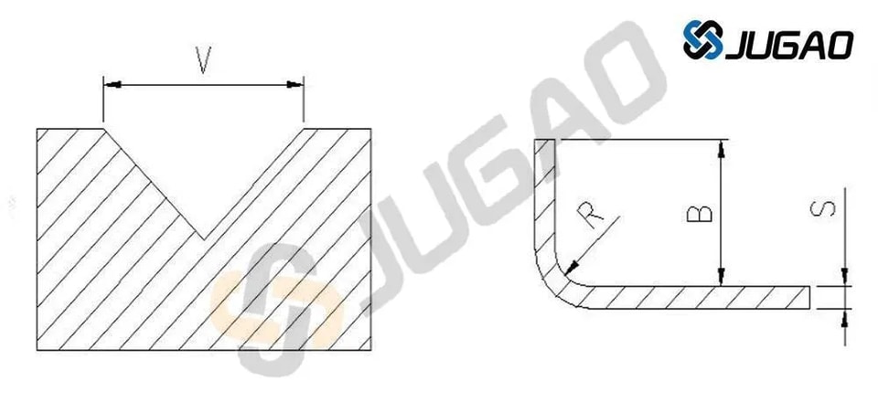
V bending slot width
R bending radius
B minimum bending height
S sheet thickness
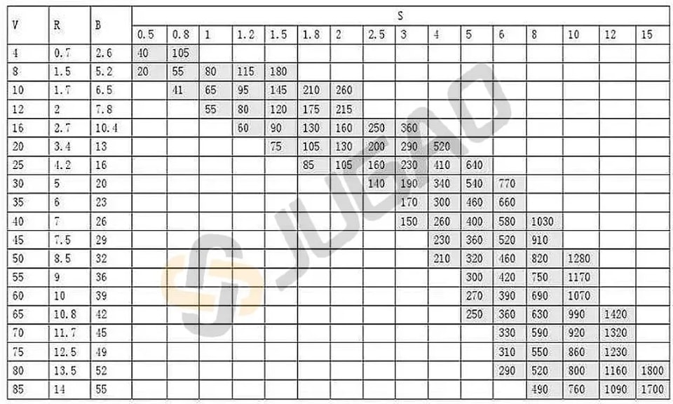
Note: The gray data in the table is the pressure P (kN/m) required for bending. The maximum pressure of the bending machine is 1700kN. The existing bending blade V=12, 16, 25, 40, 50 are five specifications. Please refer to the existing blade and bending length to determine the bending
radius in order to calculate the accurate unfolded material length.
The above description is the pressure parameters and bending slot width of a certain bending machine. The actual application is calculated and used according to the bending machine pressure and bending slot of your own sheet metal processing plant.
Related
Keep
reading.
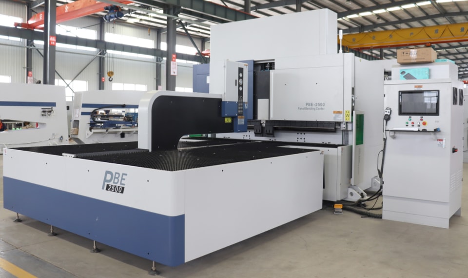 Selecting Automated Sheet Metal Bending Equipment: A Comparison Between Bending Robots and Bending Centers
 Floor-standing servo-driven follower supports for press brakes mitigate sagging during the bending of long sheets
 What factors must be considered when purchasing a stainless steel press brake?
 Common Problems with Servo Motors in Use
 Can a CNC Press Brake Bend Your Box? Check Bend Sequence, Tool Clearance and Part Removal
 How to Evaluate a Press Brake Manufacturer: A Buyer’s Evidence Checklist
 How to Choose a CNC Press Brake: Start with Your Part Drawing
 Hydraulic Press Brake Operation Instructions
 Core Structure and Working Mechanism of Profile Bending Machines
 Profile Bending Machine: Core Equipment for Precision Plastic Forming
 How to Choose Dies for CNC Bending Machines
 Detailed Explanation of CNC Bending Machine Operation and Maintenance Standards
Engineering review
Send a drawing.
Get an engineer.
Standard selections answered within 4 hours. Parts outside the rules get a written process review within 24 hours.
- Part drawing: DXF, DWG, STEP or PDF
- Material and thickness
- Longest bend or cut length
- Yearly volume
Write to info@ntjugao.com or message the factory on WhatsApp +86 132 2211 1178.
Drawings (DXF, DWG, STEP, PDF): attach them to an email to info@ntjugao.com, quoting your name.