- tel:+86-13222111178
- email:info@ntjugao.com


Quick and Easy Repair for E21 OUT OF UDP Alarm Fault
Quick and Easy Repair for E21 OUT OF UDP Alarm Fault

Table of Contents
• Step-by-Step Guide to Fixing the E21 OUT OF UDP Alarm
• Check the Slide Position
• Check the Limit Switch
• Common Causes of the Alarm
• Troubleshooting by Adjusting the Travel Stop
• Step 1: Loosen the Fixing Screw
• Step 2: Adjust the Travel Stop
• Step 3: Tighten the Fixing Screw
• System Verification and Normal Operation Confirmation
• Step 1: Check the System Display
• Step 2: Observe the Relay Indicator Light
• Step 3: Final Fault Confirmation
• Summary
Are you troubled by the E21 OUT OF UDP alarm? This fault is usually triggered when the slide is not at the Top Dead Center (TDC) position. No complicated operations are needed; you can quickly restore normal equipment operation by adjusting the slide position following the methods in this document.
In the E21 system, the OUT OF UDP alarm is mainly caused by the slide failing to reach the Top Dead Center (TDC), mostly due to abnormalities in the limit switch or travel stop. Fixing this fault only requires three steps: verify the slide position, adjust the travel stop, and check the status of the relay indicator light. Follow the process to get the equipment back up and running.
Next, a detailed explanation of the repair steps is provided to help you quickly resolve the E21 system alarm fault and restore equipment operating efficiency.
Step-by-Step Guide to Fixing the E21 OUT OF UDP Alarm
When the E21 system triggers the OUT OF UDP alarm, the root cause is that the slide cannot reach the Top Dead Center (TDC), resulting in abnormal equipment operation, production downtime, and reduced work efficiency. Mastering the troubleshooting and repair methods for this fault is key to ensuring continuous and stable production.
When starting troubleshooting and repair, press the foot switch to raise the slide to the highest position, and focus on checking whether the limit switch and travel stop are in contact—this is the most common cause of the OUT OF UDP alarm. If the limit switch is not triggered properly, the system will automatically display the alarm prompt.
Check the Slide Position
First, press the foot switch to drive the slide upward to the maximum height, and keep holding the switch until the slide stops completely. Then carefully confirm whether the slide has reached the Top Dead Center (TDC), which is the limit position of the slide’s upward movement, indicating the slide is fully raised. Confirming this accurate position is the foundation for normal subsequent operation, processing accuracy, and operational stability of the equipment.
Check the Limit Switch
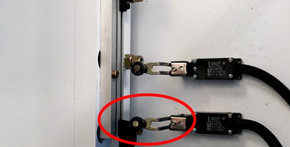
Normal equipment operation relies on effective contact between the limit switch and the travel stop. The limit switch is responsible for accurately detecting the travel position of the slide. If the two cannot make normal contact, the control system will not receive the slide position feedback signal, directly leading to abnormal equipment operation and action errors. Regular inspection and calibration of the limit switch and travel stop are necessary maintenance tasks to maintain precise equipment operation.
Common Causes of the Alarm
When the slide fails to reach the designated sensing point, the system triggers the OUT OF UDP alarm, which is a safety protection mechanism of the equipment, indicating an abnormal operating status that requires timely handling by the operator. When troubleshooting this alarm, prioritize checking whether the travel stop needs adjustment, as the alignment accuracy of the component directly affects equipment operating efficiency, and excessive deviation may also pose potential safety hazards. Timely alarm handling ensures the safe and stable operation of the bending machine and minimizes downtime to the greatest extent.
Troubleshoot and locate misalignment issues by following the above steps to ensure the slide is at the Top Dead Center position, and the OUT OF UDP alarm can be cleared.
Troubleshooting by Adjusting the Travel Stop
If the limit switch and travel stop cannot make normal contact, simply adjusting the travel stop will solve the problem. This simple operation allows the slide to smoothly reach the Top Dead Center (TDC) and eliminate the alarm fault.
Core operation for adjusting the travel stop: loosen the fixing screw, move the stop to the standard position, and then retighten the screw. After adjustment, the system will display that the slide is within the soft limit range, and the relay indicator light will turn on normally.
Step 1: Loosen the Fixing Screw
First, locate the fixing screw on the travel stop, which is usually on the side or bottom of the stop for easy operation. Use a corresponding wrench or screwdriver according to the screw type and gently loosen the screw—there is no need to remove it completely, as full disassembly may cause component misalignment and additional faults. Only loosen it enough to move the stop, which ensures smooth position adjustment while maintaining the basic fixed state of the stop. Take care to avoid damaging equipment components during operation.
Step 2: Adjust the Travel Stop
Gently move the travel stop to the precise position: ensure the limit switch can stably contact the travel stop when the slide reaches the Top Dead Center (TDC). This adjustment directly determines equipment operating accuracy, and even slight deviations may cause problems such as bending angle errors and equipment damage. After adjustment, repeatedly check the alignment of the stop to ensure a stable position. A subsequent test run is essential to verify whether the equipment can operate efficiently and normally.
Step 3: Tighten the Fixing Screw
After calibrating the travel stop into place, firmly tighten the fixing screw to prevent misalignment and operational faults caused by stop displacement during equipment operation. Use a tool to apply an appropriate torque to tighten the screw, ensuring it is secure but not over-tightened to avoid damaging the threads or the stop itself. A securely fixed stop guarantees processing accuracy and operational reliability, enabling continuous and stable equipment operation. After tightening, check the tightness of the screw again and proceed to the next step only after confirmation.
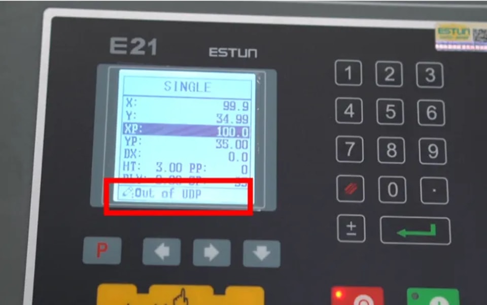
System Status Confirmation
After adjusting the travel stop, the system will prompt that the slide is within the soft limit range, which is an important verification step for fault repair.
System Verification and Normal Operation Confirmation
After adjusting the travel stop and resetting the slide, a comprehensive system verification is required to ensure the equipment returns to normal operating status.
Check the system display to confirm the slide is within the soft limit range, observe whether the relay indicator light is on, and confirm that the OUT OF UDP alarm has been completely eliminated.
Step 1: Check the System Display
After adjusting the travel stop, check the equipment system display to confirm the slide position is within the set soft limit range. A normal display indicates accurate and effective stop adjustment, and the equipment is ready for safe operation. Real-time monitoring via the display allows quick judgment of adjustment effects and timely detection of potential problems. Precise alignment not only improves equipment operating efficiency but also ensures full operational safety.
Step 2: Observe the Relay Indicator Light
A normally lit relay indicator light means effective contact has been achieved between the limit switch and the travel stop, which is the core signal of normal system operation and also indicates that the limit switch can be accurately triggered when the slide reaches the designated position. The lit light confirms successful component alignment and prevents safety risks such as slide overtravel and mechanical failures. If the light does not turn on, readjust the travel stop or troubleshoot limit switch faults to ensure equipment performance meets standards.
Step 3: Final Fault Confirmation
Check whether the OUT OF UDP alarm in the system has been cleared. Clearing indicates that the equipment operating parameters have returned to the qualified range and the adjustment of the travel stop and limit switch is effective. If the alarm persists, readjust the travel stop following the process and check the limit switch for wear, misalignment, or other faults. Timely handling of these issues is critical to maintaining efficient and stable equipment operation.
Summary
Adjust the travel stop and calibrate the slide position following the steps in this document to resolve the OUT OF UDP alarm fault in the E21 system and restore normal equipment operation. Adjusting the travel stop to the standard position ensures normal triggering of the limit switch and travel stop, which is key to accurate system operation. After adjustment, the system will display the slide within the soft limit and the relay indicator light will turn on, indicating complete fault repair.
It should be noted that this adjustment is not a one-time fix. Regular maintenance of the slide, travel stop, and limit switch can effectively prevent the recurrence of the OUT OF UDP alarm. Long-term equipment operation causes component wear that affects position accuracy, so regular checks of slide alignment and limit switch operating status are crucial for long-term stable equipment operation. Proper maintenance of these components reduces downtime losses, keeps the E21 equipment in optimal operating condition, lowers the incidence of alarm faults, and extends equipment service life.
Contact Us