- tel:+86-13222111178
- email:info@ntjugao.com


Key points for electrical connections on a pipe bending machine: Incorrect connections can lead to alarms at best, and machine failure at worst.
Key points for electrical connections on a pipe bending machine: Incorrect connections can lead to alarms at best, and machine failure at worst.

Electrical connections may seem like simple plugging in wires and tightening screws, but incorrect connections on certain wires on a pipe bending machine can cause it to either not start or malfunction. Pay close attention to the following points when making connections.

1. Main Power Supply: Incorrect Phase Sequence Causes Pump Reversal
Most pipe bending machine main motors are three-phase 380V. Reversing the phase sequence causes the oil pump to reverse—no oil can be pumped, and the system cannot build pressure. Most dangerously, on some models, the bending arm may fall off under gravity, posing a significant risk of injury.
Correct Procedure: After connecting the wires, briefly start the motor to check if the rotation direction matches the arrow on the oil pump. Using a phase sequence meter is even safer. A main switch and fuse or circuit breaker should be added to the incoming line.
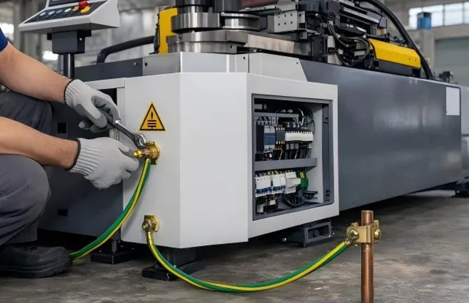
2. Motor and Driver: Secure Grounding is Essential
The grounding wires for the servo motor and frequency converter cannot be omitted. Poor grounding will cause interference with the encoder signal, resulting in fluctuating angles. Motor power lines and encoder feedback lines should be routed in separate cable trays, not bundled together, otherwise, high current will interfere with low signals.
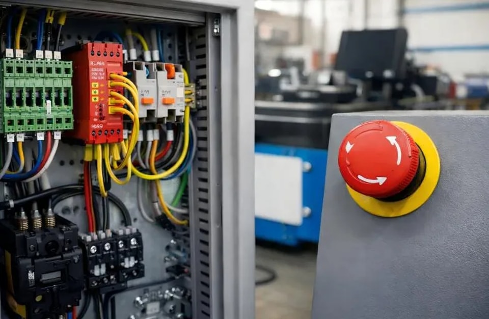
3. Emergency Stop Circuit: Connect All Emergency Stop Buttons in Series
Pipe bending machines have multiple emergency stop buttons (operation panel, handheld box, control cabinet door). They must be connected in series to the PLC's safety input or the contactor's control circuit. After connecting, test each component individually: Upon testing any one component, all moving parts must be immediately powered off and stopped.
4. Sensors and Limit Switches: Distinguish Between Normally Open and Normally Closed Switches
If proximity switches or limit switches are connected incorrectly (normally open or normally closed), the PLC will not receive a signal, and the machine will either not move or overtravel and crash. After connecting correctly, monitor the I/O signals in manual mode to confirm the state flips upon triggering.
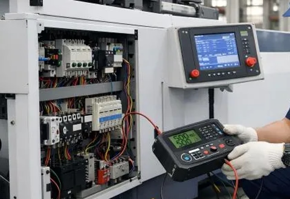
5. 24V Power Supply: Sufficient Capacity, Correct Polarity
The PLC, sensors, and touchscreen all use 24V DC power. The switching power supply capacity must be greater than the total capacity of all loads (leaving a 30% margin). Reversing the 24V positive and negative terminals will burn the circuit board—check with a multimeter after connection before powering on. When multiple sensors share a power supply, the positive and negative terminals must be connected in parallel, not in series.
6. Encoder Cable: Single-End Grounding of Shielding Layer
The signal cable for the angle encoder must use twisted-pair shielded cable. The shielding layer should be grounded at one end (PLC or driver), with the other end left floating. Grounding both ends of the shielding layer will create ground loops, introducing interference.
7. Communication Cable: Matching Termination Resistors
If the pipe bending machine has bus communication (such as Profinet, EtherCAT), the communication cable must conform to the standard, and both ends of the bus must be connected to terminating resistors (or software-enabled terminating resistors). Otherwise, signal reflection will occur, data packet loss will happen, and the equipment will disconnect intermittently.
8. Electrical Cabinet Wiring: Separate High-Voltage and Low-Voltage Cables, Clear Wire Numbers
220V/380V high-voltage and 24V low-voltage signal cables must be run in separate cable trays, with a minimum spacing of 10cm to avoid electromagnetic interference. Each cable should be fitted with a wire number conduit at both ends, and the terminal blocks should be labeled—those checking the wiring later will thank you.
9. Motor Overheat Protection: The thermal relay setting must be accurate.
The thermal relay setting current should be set to 1.05 to 1.1 times the motor's rated current. Setting it too high will prevent the motor from tripping even if it burns out; setting it too low will cause frequent malfunctions.
10. Pre-Test Check: Three Confirmations
Confirm all grounding wires are connected.
Confirm three-phase voltage is within the normal range.
Confirm the emergency stop circuit is functioning correctly.
The core of electrical connections is not "being able to conduct electricity," but rather "safety, interference resistance, and ease of maintenance." Following the wiring diagrams is fundamental, but understanding the underlying principles is essential to avoid mistakes.
Contact Us