- tel:+86-13222111178
- email:info@ntjugao.com


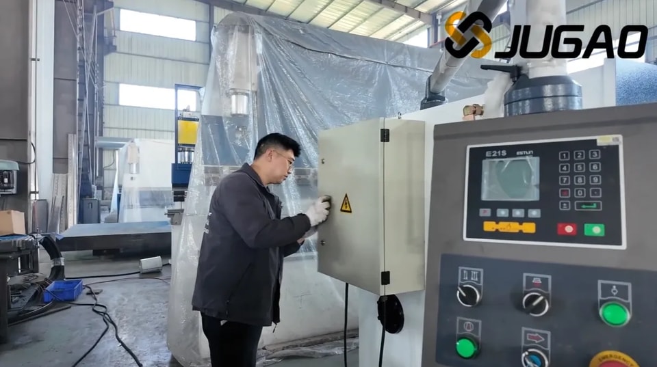
How to Operate JUGAO Guillotine Shearing Machine (E21S)
How to Operate JUGAO Guillotine Shearing Machine (E21S)

Table of contents
1. Oil Filling and Cable Connection
○ Proper Hydraulic Oil Tank Filling
○ Correct 3-Phase Power Supply Connection
○ Turn on the main power supply
○ Activate the machine power switch
○ Connect the foot pedal switch to the machine
○ Power on the control system
○ Release emergency stop and start the oil pump
○ Verify main motor rotation direction
○ Confirm correct rotation
○ If rotating counterclockwise
○ Trigger emergency stop
○ Swap two power wire connections
2. Machine Startup Procedure
○ Switch on the machine main power
○ Turn the power control key to ON
○ Release emergency stop and start oil pump
○ Wait for system initialization
3. System Parameter Operation
○ Single cutting mode
○ Manual jog control
○ Speed adjustment safety guidelines
○ Navigate cursor to XP parameter
○ Enter value 100 and confirm
○ Press the Run button
○ Continuous automatic mode
○ Press P button, select/program number and confirm
○ Set program steps to 3 and confirm
○ Enter step 1 setup interface
○ Select XP, input 150, confirm
○ Enter step 2 setup interface
○ Select XP, input 100, confirm
○ Enter step 3 setup interface
○ Press the Run button
4. Cutting Operation
○ Single mode cutting
○ Place metal sheet correctly
○ Align sheet with backgauge fingers
○ Step on foot pedal to cut
5. Dimensional Inspection
○ Measure raw sheet length (455)
○ Measure finished sheet length (355)
6. Routine Maintenance
○ Troubleshooting blade holder malfunctions
○ Check accumulator pressure gauge
○ Assistant holds the refilling button
○ Reset shear to normal working status
7. Shutdown Procedure
○ Press the red Stop button
○ Activate emergency stop button
○ Turn off main power switch
Mastering the operation of the JUGAO Guillotine Shearing Machine (E21S) is key to efficient and precise metal cutting. This guide simplifies complex parameter settings to help you achieve perfect cuts with ease.
To operate the JUGAO E21S guillotine shearing machine: first power on the unit and configure cutting parameters via the E21S controller. Adjust blade clearance, backgauge position and cutting length to match your material specifications. Securely position the metal sheet and start the cutting cycle for accurate results.
Below is a detailed, step-by-step operational guide for seamless cutting performance.
1. Oil Filling and Cable Connection
Proper Hydraulic Oil Tank Filling
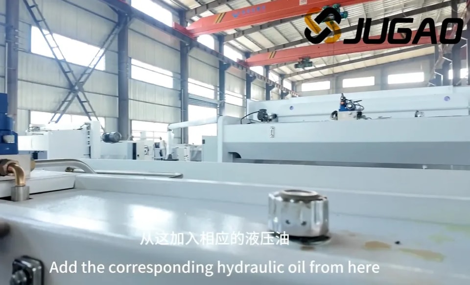
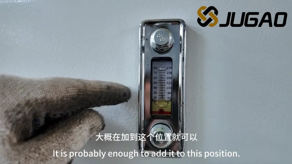
To maintain peak hydraulic system performance, use only anti-wear hydraulic oil that meets manufacturer specifications. Locate the dedicated oil filling port on the machine, then slowly pour oil into the tank while monitoring the level gauge. Avoid overfilling or underfilling, as both conditions impair machine function. High-grade anti-wear hydraulic oil reduces component wear, extends service life and ensures stable hydraulic operation. Always follow safety instructions and machine manual requirements during this process.
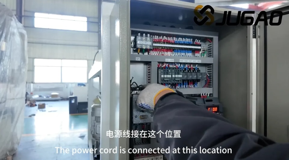
Correct 3-Phase Power Supply Connection
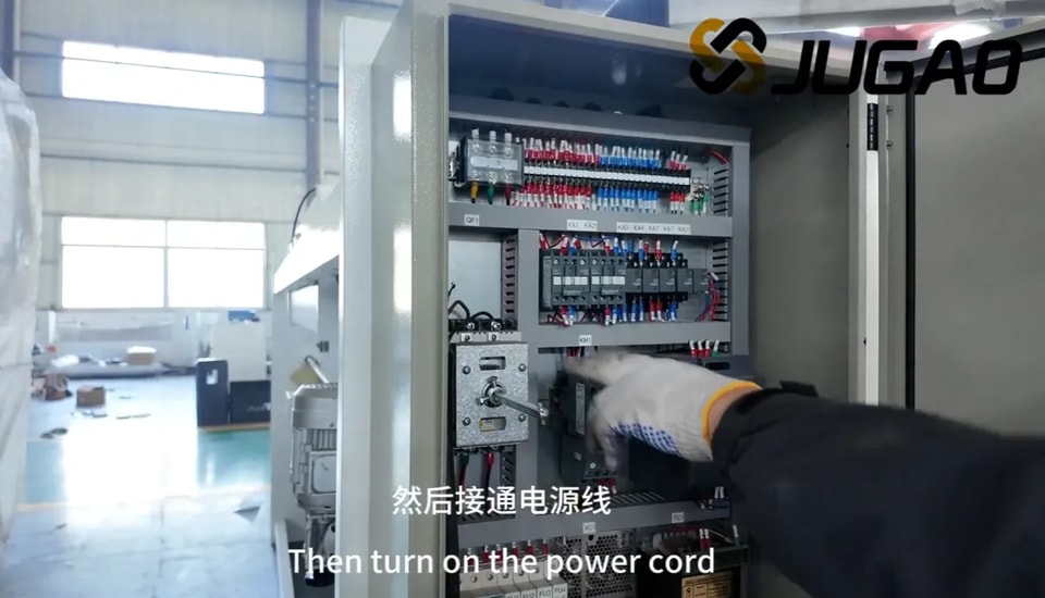
For safe 3-phase power connection, confirm the supply voltage and frequency match the machine’s rated parameters. Turn off the main power supply and inspect terminals for damage. Use insulated cables to connect the machine’s power wires to L1, L2, L3 phases, and firmly attach the grounding wire to prevent electric hazards. Restore power and verify normal machine operation. Adhere strictly to electrical safety standards to avoid accidents or equipment damage.
Turn on the main power supply
Locate the main power switch near the control panel and switch it to ON. Check that all control panel indicators light up normally. This step readies the machine for operation. Always wear personal protective equipment and clear the cutting area of obstacles before proceeding.
Activate the machine power switch
Confirm complete power connection and released emergency stop before turning the main power switch (usually on the side/rear panel) to ON. Observe the control panel for startup signals and verify all safety devices are functional. Proper power activation ensures operational readiness and reduces error risks.
Connect the foot pedal switch to the machine
Disconnect machine power for safety first. Find the pedal switch port at the machine base, align and plug in the connector securely to avoid loose contact during operation. Arrange the cable to avoid entanglement or obstruction. Restore power and test the pedal function. Correct connection ensures responsive control and minimizes operational faults.
Power on the control system
Locate the control system power switch on the panel. Confirm no loose items near the cutting zone, then flip the switch to ON. Listen for startup tones or check indicator lights to confirm power-on success. Double-check system readiness on the display before further operation.
Release emergency stop and start the oil pump
Fully release the emergency stop button to lift the safety shutdown state. Press the oil pump start button to build hydraulic pressure, which enables normal machine movement. Confirm the pump runs smoothly before proceeding to subsequent operations.
Verify main motor rotation direction
Incorrect motor rotation causes operational failure, efficiency loss or equipment damage. Briefly power on the machine and check rotation against the marked arrow on the body or manual. If rotation is wrong, adjust wiring per instructions or contact a technician. Regular rotation checks preserve performance and service life.
Confirm correct rotation
The main motor must rotate clockwise for standard operation. Counterclockwise rotation indicates a wiring error and may create safety risks or mechanical damage. If abnormal rotation is found, stop the machine immediately and correct the wiring.
If rotating counterclockwise
Counterclockwise rotation signals a wiring issue. Turn off power completely first. For 3-phase motors, swapping any two power wires reverses rotation direction. If problems continue, inspect the controller or consult professional maintenance.
Trigger emergency stop
The emergency stop button is a critical safety component. Press it firmly to cut all power and halt movement immediately in case of malfunction, misalignment or danger. Ensure the emergency stop works properly before each operation.
Swap two power wire connections
Disconnect all power before wiring adjustment. Use insulated tools to loosen the terminals of two power lines, swap their positions and retighten securely. Double-check connections before powering on to ensure safe and correct operation.
2. Machine Startup Procedure
Switch on the machine main power
Confirm stable cable connections, then turn the main power switch to ON. Wait for the control system to initialize and check for error messages. Resolve warnings per the manual before continuing.
Turn the power control key to ON
Insert and turn the power control key clockwise to activate the control system. Verify all panel indicator lights function normally. This step initializes internal systems and prepares the machine for work.
Release emergency stop and start oil pump
Release the emergency stop switch to reset safety interlocks. Start the oil pump to supply hydraulic power. Ensure stable pump operation before moving to parameter setup.
Wait for system initialization
Allow the system to complete self-check and component initialization. Do not interrupt the loading process to avoid system errors. If loading takes too long, check power supply, connections or software status.
3. System Parameter Operation
Single cutting mode
Single mode supports one cut at a time, ideal for custom or small-batch jobs. Select Single mode, set parameters, position material and execute cutting. Double-check settings and safety conditions before each cut.
Manual jog control
Enter the manual operation page to adjust axis positions manually. Monitor X, A, G axis real-time data on the display for precise positioning.
Speed adjustment safety guidelines
Adjust speed gradually in increment or decrement directions. Slow speed is recommended for setup and delicate materials to improve control accuracy and protect machine parts.
Navigate cursor to XP parameter
Use directional keys or jog dial to move the cursor to the XP parameter on the controller screen. Accurate positioning ensures correct parameter input.
Enter value 100 and confirm
Input the value 100 for the XP parameter and press confirm. Verify the displayed value matches your input to ensure cutting accuracy.
Press the Run button
After confirming all parameters and material placement, press Run to start the cutting cycle. Monitor operation for abnormalities and keep safety guards in place.
Continuous automatic mode
Continuous mode runs automatic repeated cycles, suitable for mass production. Pre-set programs ensure consistent cuts and reduce manual intervention. Keep safety systems activated during continuous operation.
Press P button, select/program number and confirm
Press the P button to open the program menu. Select an existing program or enter a program number directly, then confirm your choice.
Set program steps to 3 and confirm
On the program settings page, set the total steps to 3 and confirm. This defines the multi-step cutting sequence.
Enter step 1 setup interface
Access the first step configuration page to define cutting dimensions for the first cycle.
Select XP, input 150, confirm
Choose the XP parameter, enter 150 and save the setting.
Enter step 2 setup interface
Open the second step configuration page for the next cutting dimension.
Select XP, input 100, confirm
Set XP to 100 and confirm the value.
Enter step 3 setup interface
Navigate to the third step configuration screen to finish program setup.
Select XP, input 120, confirm
Input 120 for the XP parameter and confirm to complete programming.
Press the Run button
Check the full program and material positioning, then press Run to start continuous automatic cutting.
4. Cutting Operation
Single mode cutting
In Single mode, each pedal press completes one cut. Adjust and align material before every cut for high precision.
Place metal sheet correctly
With the machine powered off, position the sheet against the backgauge or front guide. Ensure firm, stable placement to prevent shifting during cutting.
Align sheet with backgauge fingers
Push the sheet firmly against the stop fingers to guarantee consistent positioning and accurate cut length. Recheck alignment before cutting.
Step on foot pedal to cut
Ensure correct sheet placement, then press the foot pedal firmly to start cutting. Keep hands clear of the blade area. Release the pedal once the cut finishes.
5. Dimensional Inspection
Measure raw sheet length (455)
Use a precision measuring tool to check the original sheet length (target: 455) before cutting to ensure material meets requirements.
Measure finished sheet length (355)
After cutting, measure the workpiece dimension (target: 355). If deviation occurs, adjust machine parameters and re-test. Consistent inspection reduces waste and ensures quality.
6. Routine Maintenance
Troubleshooting blade holder malfunctions
If the blade holder fails to cut, lift or respond to the pedal: inspect blade wear, clear obstructions in the holder, check hydraulic pressure and leaks, and verify foot pedal wiring and function.
Check accumulator pressure gauge
Slowly open the ball valve and observe the accumulator pressure gauge. Confirm pressure stays within the recommended range. Abnormal readings indicate hydraulic system issues.
Assistant holds the refilling button
Have a second operator press and hold the refilling button to stabilize oil flow during hydraulic replenishment. This ensures consistent system pressure and smooth operation.
Reset shear to normal working status
When the accumulator pressure reaches approximately 10, close the ball valve and release the refilling button simultaneously. The blade holder should return to the home position, and the machine is ready for normal use.
7. Shutdown Procedure
Press the red Stop button
Locate and press the red Stop button to terminate all running actions. Ensure full machine stop before cleaning or maintenance.
Activate emergency stop button
Press the emergency stop button to lock the machine in a safe state and prevent accidental startup.
Turn off main power switch
Turn off the main power switch at the control panel or electrical box. Confirm all indicators are off to ensure complete power disconnection before maintenance, adjustment or leaving the workplace.
https://www.youtube.com/watch?v=PARJsCquKKM&list=PLvrBvUrquBVoLKsgzduUSjVfXmhq18l3M&index=15&t=142s
Contact Us