- tel:+86-13222111178
- email:info@ntjugao.com


How to Fix No Pressure Fault in JUGAO Press Brake
How to Fix No Pressure Fault in JUGAO Press Brake

Table of contents
1. Fault Description
2. Hydraulic System
3. Fault Analysis and Troubleshooting
Encountering a no pressure fault on a JUGAO press brake can directly cause production shutdown. This guide helps you quickly locate and resolve the fault to ensure stable and efficient operation of the equipment.
The no-pressure malfunction of press brakes is mostly triggered by insufficient hydraulic oil, damaged hydraulic parts and other issues. This document will elaborate on the diagnosis and repair steps of the fault, so as to maintain the stable performance of the machine.
After clarifying the potential causes, we will explain the specific solutions to the no-pressure fault in detail below.
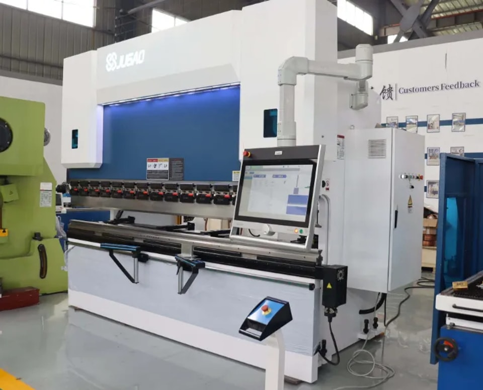
CNC hydraulic press brake is mainly used for sheet metal bending, which is composed of frame, slider, worktable, hydraulic cylinder, hydraulic proportional servo system, position detection system, CNC system and electrical system. This type of press brake can keep the slider synchronized (parallel to the worktable) under no-load speed, working speed and return stroke, and achieve high-precision positioning at the stroke end. Therefore, it is widely used in component bending processing in automobile, shipbuilding, container, engineering machinery, construction machinery, metal structure, light pole, power pole and other industries.
This paper will analyze the hydraulic system of CNC hydraulic press brake, sort out the possible causes of no bending pressure and other faults, and introduce the working principle of prefill valve and targeted troubleshooting methods.
1. Fault Description
2. 
During the operation of CNC hydraulic press brake, the slider (ram) controlled by CNC system and hydraulic servo system needs to go through six stages to complete a single bending action: fast descending, slow descending, bending and pressure maintaining, pressure relief, fast ascending and stopping at top dead center. This paper simplifies the six stages into three stages: fast descending, bending and fast returning.
The fault phenomenon of the press brake in this case is: the slider can move down quickly, but the pressure is insufficient during bending, making it impossible to finish the bending work normally.
2. Hydraulic System
Hydraulic Principle Diagram
1—prefill valve 2—proportional servo valve 3—relief valve
4—cartridge valve 1 5—proportional relief valve 6—cartridge valve 2
7—oil filter device 8—hydraulic pump
Fast Downwards
When 4Y5 (cross) and 4Y3 are powered on, the oil in the lower cavity of the hydraulic cylinder flows back to the oil tank rapidly through cartridge valve 1 and proportional servo valve, and the supporting pressure of the slider disappears. Driven by its own weight, the slider drops rapidly, forming instant negative pressure in the upper cavity of the hydraulic cylinder, which sucks open the prefill valve. A large amount of oil from the oil tank enters the upper cavity of the hydraulic cylinder through the prefill valve, realizing the fast descending of the slider.
Bending
When the slider descends to the switching point, 4Y3 is powered off, the cartridge valve is closed, and the oil in the lower cavity of the hydraulic cylinder builds pressure through the relief valve to prevent the slider from falling freely. At this time, 1Y1 is powered on to make the proportional relief valve establish system pressure, 1Y2 is powered on to close the prefill valve, and the oil enters the upper cavity of the hydraulic cylinder through the proportional servo valve, pushing the slider to move down and complete the bending action.
Fast Retract (Fast Upwards)
4Y3 is powered on, cartridge valve 1 is opened, and 4Y5 (straight through) is powered on. At this time, the oil output by the hydraulic pump enters the lower cavity of the hydraulic cylinder through the proportional servo valve and cartridge valve 1, while 1Y1 remains powered on, and the proportional relief valve continues to build pressure. Meanwhile, 1Y2 is powered off, the prefill valve is opened under the pressure of the control oil circuit, the oil in the upper cavity of the hydraulic cylinder flows back to the oil tank quickly through the prefill valve, and the slider completes the fast return action.
3. Fault Analysis and Troubleshooting
Combined with the fault phenomenon and hydraulic system schematic diagram, the root causes of insufficient bending pressure of the press brake are summarized as follows:
Fault Causes
• The 1Y1 solenoid of the proportional relief valve in the pressure control valve group is not powered on, making the proportional relief valve work as an ordinary relief valve, and the system cannot establish effective working pressure.
• The tapered hole of the cartridge valve is worn or the sealing element is invalid, resulting in incomplete closure of the valve port. When the system builds pressure, the oil directly flows back to the oil tank through the cartridge valve, leading to pressure loss.
• The prefill valve fails to close normally, the valve core is damaged or the seal is damaged, causing the upper cavity of the hydraulic cylinder to communicate with the oil tank through the prefill valve cavity. The oil leaks back to the oil tank via the prefill valve, resulting in insufficient bending pressure.
Following the troubleshooting sequence from simple to complex, the specific inspection and repair steps are as follows:
Troubleshooting Steps
1. Check the power-on state of the proportional relief valve in the pressure control valve group. During the bending operation, observe whether the 1Y1 indicator light is on and whether the proportional relief valve acts normally. If normal, the fault of the proportional relief valve can be excluded.
2. Inspect cartridge valve 2 in the pressure control valve group, disassemble the valve body, check the wear degree of the tapered hole, clean the valve core and reinstall it. If the pressure is still insufficient, the fault of the cartridge valve can be temporarily excluded.
3. Check the solenoid directional valve of the oil circuit. The solenoid valve should be kept closed during bending, and the command for closing the prefill valve is normal, with no abnormality found in the solenoid directional valve.
4. Disassemble and inspect the prefill valve. It is found that the locking bolt at the valve end is loose and falls off, and the pilot valve core is damaged, making the prefill valve unable to close tightly, so the bending pressure cannot be established normally.
If you need further technical support, please feel free to contact us.
Contact Us