- tel:+86-13222111178
- email:info@ntjugao.com


Rapid diagnosis and handling of alarm faults in ET series
Rapid diagnosis and handling of alarm faults in ET series

Are you struggling with alarm issues on your ET series all-electric servo bending machine? You've come to the right place. This article will provide a detailed guide on how to quickly troubleshoot ET series alarm problems, ensuring smooth and efficient production operations. While ET series alarms are common, with the right approach, you can quickly resolve them and restore your equipment to optimal performance. Whether you're new to this system or looking to optimize your troubleshooting process, this guide will provide key steps to help you effectively handle various alarm issues.
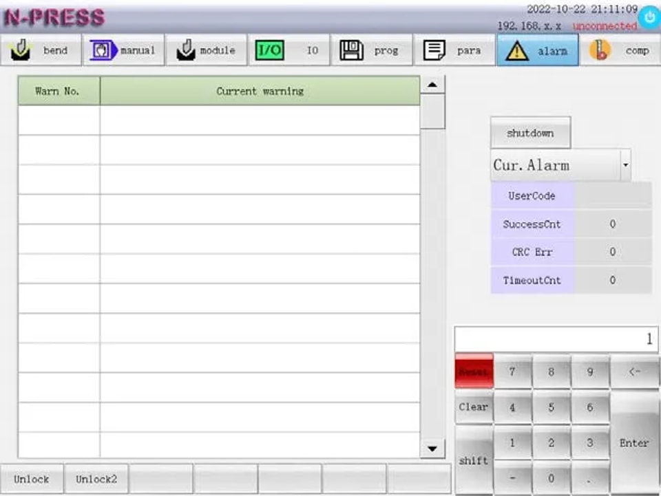
Step 1: Accessing the ET Series Alarm Interface
Click on the ‘alarm‘ function key to access the interface and view all ET Series Alarm details. This interface provides a comprehensive display of current alarms, alarm records, and other crucial statistics like success times, verification errors, and timeout times.
Analyze Alarm Records
Understand the frequency and type of alarms occurring by reviewing past records. Pay special attention to the number of ET Series Alarm verification errors and timeout issues as these indicate underlying communication problems with the IO module.
l Success Times: Reflects the number of successful communications between the system and the IO module, indicating the system’s overall communication health.
l Verification Errors: Displays the number of verification errors in the data communication between the system and the IO module. A high number of errors could suggest data integrity issues that need immediate attention.
l Timeout Times: Shows the number of communication connection errors between the system and the IO module, signaling potential disruptions in data transfer that could affect machine operations.
Step 2: Interpreting ET Series Alarm Status
To effectively handle the ET Series Alarm, first check the alarm information for error (ERRxxx) and warning (ALMxxx) codes. The most recent alarms are listed as ‘Current alarm‘. Follow the instructions to resolve issues and press the reset key to clear the alarm, restoring system normalcy.
If a CNC system failure occurs, alerts will display up to five current alarms. Record the warning code and take the recommended action, or contact professional maintenance personnel if necessary.
By following these steps, you can troubleshoot the ET Series Alarm quickly, reducing downtime and boosting productivity.
Step 3: Resolving ET Series Alarm Issues
ET Series Alarm-Error Code
ERR001: Safety Light Curtain Alarm
Cause: When the y-axis runs downward, the human body or other objects enter the light curtain area.
Treatment: Verify if anyone is in the light curtain area or if the safety grating is malfunctioning.
ERR002: Y1 and Y2 Axis Position Deviation
(Alarm will be prompted when it is generated in manual mode, and alarm will be prompted when it is generated in bending.)
Cause: The absolute coordinate value deviation of Y1 axis and Y2 axis exceeds the maximum deviation setting value of Y axis.
Treatment: First, check whether the position error of the Y1 and Y2 axes is out of tolerance. Next, verify whether the linear encoder is functioning properly or if it is invalid. Finally, examine whether there is a failure in the mechanical transmission and whether the allowable value of the position deviation for the system parameters Y1 and Y2 is set too small.
ERR003: Alarm when the Pressure Exceeds the Maximum Allowable Value of the Machine Tool
Cause: Wrong mold or material selected.
Treatment:
1. Verify Mold and Material Selection:
l Ensure the mold and material are selected correctly.
2. Check Bending Pressure:
l Examine if the bending pressure in the program, synthesis, and programming interface is too high.
3. Pressure Assessment:
l If the displayed pressure exceeds the machine tool’s allowable limit:
l Replace the mold or material.
l If the displayed pressure is within the permissible range:
l Verify the correct setting of the upper and lower die heights.
ERR004: Alarm When the Pressure Exceeds the Allowable Value of the Mold
Cause: Wrong mold or material selected.
Treatment:
1. Check whether the mold and material are selected correctly.
2. Verify if the bending pressure in the program, synthesis, and programming interface is too large.
l If the displayed pressure exceeds the allowable pressure of the mold, replace the mold or material.
l If the displayed pressure is within the allowable range of the mold, ensure the upper and lower mold heights are set correctly.
ERR005: Pressure Limit for Bending Exceeded
Cause: Wrong mold or material selected.
Treatment:
1. Check whether the mold and material are selected correctly.
2. Verify if the bending pressure in the program, synthesis, and programming interface is too large.
3. If the displayed pressure exceeds the allowable pressure of the mold, please replace the mold or material.
4. If the displayed pressure is within the allowable range of the mold, ensure the upper and lower mold heights are set correctly.
ERR006: Pressure Detection Communication Timeout
Cause: Communication between system and IO board timeout.
Treatment: Ensure correct IO board type settings and proper 485 communication line connections.
ERR007: Pressure Detection Channel Fault
Cause: The analog value is too low.
Treatment: Confirm correct analog signal line connections.
ERR008-ERR12: X-Z2 Axis Super Positive Hard Limit
(Alarm will be prompted when bending; alarm will be prompted when manual mode is generated)
Cause: The positive limit switch of each axis is triggered during bending.
Treatment:
1. Check whether each axis has entered the positive limit switch area.
2. Verify if the positive limit switch of each axis is malfunctioning.
3. Use the manual control interface to move each axis out of the limit switch area.
ERR013-ERR017: the X-Z1 Axis Exceeds the Nnegative Hard Limit
(Alarm will be prompted when bending and zero point finding; the alarm will be prompted when manual mode is generated)
Cause: the negative limit switch of each shaft is triggered during bending.
Treatment:
1. Move each axis in the manual control interface to exit the limit switch area.
2. Check whether each shaft enters the negative limit switch area.
3. Check whether the negative limit switch of each shaft fails.
ERR018-ERR022: X-Z2 Axis Super Positive Soft Limit
Cause: The machine coordinate of each axis exceeds the positive soft limit position set by the system parameter.
Treatment: Check whether the positive soft limit position of each axis set by the system parameter is appropriate.
ERR023-ERR027: X-Z1 Axis Over Negative Soft Limit
Cause: The machine coordinate of each axis exceeds the negative soft limit position set by the system parameter.
Treatment: Check whether the negative soft limit position of each axis set by the system parameter is appropriate.
ERR028: Machine Tool Overdue Alarm
Cause: The machine tool is overdue.
Treatment: Please contact the supplier.
ERR029-ERR034: Alarm of Servo Driver of Each Axis
Cause: The servo driver of the corresponding axis gives an alarm or the connection of the servo driver fails.
Treatment: Check the alarm cause of the servo driver or check the connecting cable between the system and the servo driver.
ERR035-ERR040: Encoder Alarm of Each Shaft
Cause: The encoder signal of the corresponding shaft is wrong.
Treatment: Check the encoder-related signal wiring of the connecting cable between the system and the servo driver.
ERR041-ERR046: Non-Motion Mode Servo Abnormal Alarm of Each Axis
Cause: When the corresponding axis does not receive the motion command, it detects that the coordinates fed back are abnormal.
Treatment: Check the encoder connecting cable.
ERR047-ERR052: Servo Abnormal Alarm of Each Axis Motion Mode
Cause: Position tracking alarm of each axis.
Treatment: Check whether the allowable value of position tracking error is set too small.
ERR053: Power Failure Alarm
Cause: The system power supply voltage is detected to be too low.
Treatment: Check whether the power supply is normal.
ERR054: System Alarm
Cause: System internal exception.
Treatment: Please contact the supplier.
ERR055: Emergency Stop Alarm
Cause: It is detected that the emergency stop key is pressed.
Treatment: Check whether the emergency stop key is pressed.
ERR056: In Torque Limit
Cause: The maximum torque of the motor is exceeded.
Treatment: Check whether the y-axis speed or acceleration is set too large.
ERR057: The Spacing Between Z1 and Z2 is Too Small
Cause: The z-axis of manual control movement in manual control mode exceeds the safety distance of system parameter 603: z1z2.
Treatment: Check whether the parameters set by the system parameters are appropriate.
ERR059: Overdue Warning
Cause: The usable time of the system is less than 2 days.
Treatment: Contact the supplier.
ERR060: Rear Gear 2 Exceeds Negative Soft Limit
Cause: When using the rear gear 2, the x-axis machine coordinate exceeds the x-axis negative soft limit position set by the system parameter.
Treatment: Check whether the rear gear is selected reasonably.
ERR061: Safety Door Alarm
Cause: The safety door was opened during use.
Treatment: Check whether the safety door is closed.
ERR062: Air Conditioning Alarm
Cause: Failure of air conditioner.
Treatment: Check the air conditioner.
ERR063: Deflection Compensation Timeout
Cause: Deflection compensation cannot be completed for a long time.
Treatment: Check whether the deflection compensation accuracy is set too small.
ERR064: Deflection Compensation Direction Error
Cause: Deflection compensation motor rotation direction error.
Treatment: Check whether the wiring of deflection compensation motor is correct.
ERR065: Emergency Stop Alarm 1
Cause: The input signal of emergency stop alarm 1 is valid.
Treatment: Check the input signal of emergency stop alarm 1.
ET Series Alarm-Alarm Code
ALM001-ALM006 X-Z2 Axis Origin Search Failed
Cause: The system does not detect the origin signal of the corresponding axis during the search, or the origin coordinate of the corresponding axis is set incorrectly.
Treatment: Check whether the search distance of the third section of the corresponding axis in the system parameters is less than one pitch. Also, verify the origin coordinates of the corresponding axis.
ALM007-ALM011 X-Z2 Axis Super Positive Hard Limit
Cause: The positive limit switch of the corresponding shaft is triggered in manual mode.
Treatment: Check if the corresponding shaft enters the positive limit switch area or if the positive limit switch of the shaft fails. Move the corresponding axis in the manual control interface to exit the limit switch area.
ALM012-ALM016 X-Z1 Axis Super Negative Hard Limit
Cause: The negative limit switch of the corresponding shaft is triggered in manual mode.
Treatment: Check if the corresponding shaft enters the negative limit switch area or if the negative limit switch of the shaft fails. Move the corresponding axis in the manual control interface to exit the limit switch area.
ALM017-ALM021 X-Z2 Axis Super Positive Soft Limit
Cause: The forward soft limit of the corresponding shaft is triggered in manual mode.
Treatment: Move the corresponding axis in the manual control interface to exit the soft limit, and check if the soft limit setting in the system parameters is appropriate.
ALM022-ALM026 X-Z1 Axis Over Negative Soft Limit
Cause: The corresponding axis negative soft limit is triggered in manual mode.
Treatment: Move the corresponding axis in the manual control interface to exit the soft limit, and check if the soft limit setting in the system parameters is appropriate.
ALM027 Position Deviation of Y1 and Y2 Axes Exceeds the Limit
Cause: The absolute coordinate value deviation of Y1 and Y2 axes exceeds the maximum deviation setting value of Y axis in manual mode.
Treatment: Check if the position error of Y1 and Y2 axes is out of tolerance; verify if the linear encoder is invalid; check the mechanical transmission for failure. Move Y1 and Y2 in a direction that reduces the axial position deviation.
ALM028-ALM033 X-Z2 Axis Zero Position Deviation Exceeds the Limit
Cause: In the reference point mode, the machine coordinate value of the corresponding axis after the search for the origin is significantly different from the value recorded in system parameters 260-263608-609.
Treatment: Check if system parameters 260-263608-609 are set correctly.
ALM034 Lubrication Pump Warning
Cause: The output pressure of the lubrication pump is insufficient.
Treatment: Check if the lubricating grease is used up. If so, add No. 00 extreme pressure lithium base lubricating grease. If not, check if the lubricating pump is normal or if the lubricating pipe is leaking and if the signal line of the lubricating pump is connected correctly.
ALM035 Tool Not Clamped
Cause: No clamping signal of hydraulic tool holder is detected.
Treatment: Check whether the clamping signal wiring of the hydraulic tool holder is correct.
ALM036 ZLZ2 Spacing Too Small
Cause: The z-axis in manual control mode exceeds the safety distance of system parameter 603: z1z2.
Treatment: Check if the parameters set by the system parameters are appropriate.
ALM037 Safety Light Curtain Warning
Cause: The light curtain signal is detected to be valid.
Treatment: Check if the light curtain is blocked.
ALM038 Overdue Warning
Cause: The usable time of the system is less than 2 days.
Treatment: Contact the supplier.
ALM039 Deflection Compensation Positive Limit
Cause: The deflection compensation mechanism exceeds the positive limit.
Treatment: Check the movement direction of the deflection compensation mechanism and whether the limit signal connection is correct.
ALM040 Deflection Compensation Negative Limit
Cause: The deflection compensation mechanism exceeds the negative limit.
Treatment: Check the movement direction of the deflection compensation mechanism and whether the limit signal connection is correct.
ALM041 Deflection Compensation
Cause: Prompt in deflection compensation.
Treatment: Check whether the deflection compensation accuracy setting is too small.
ALM042 Y-axis Tilt
Cause: Y-axis tilt input signal is valid.
Treatment: Check whether Y1Y2 is parallel and whether the origin setting is correct.
Conclusion
In summary, the key to quickly troubleshooting ET series mold alarms lies in mastering the core steps for effectively identifying and resolving common faults. By following the procedures outlined in this article—such as checking wiring connections, calibrating system parameters, and performing routine maintenance—you will be able to minimize downtime and ensure production efficiency.
For further assistance or more detailed technical information, please feel free to contact our technical support team, JUGAO CNC MACHINE. We are ready to provide you with professional advice and additional resources to help you use our products more efficiently. You can also consult our other technical documents for further information on bending machine maintenance and performance optimization.
Contact Us