-
tel:
+86-13222111178 -
email:
info@ntjugao.com


Installation and Adjustment of Electro-Hydraulic Press Brake Dies
Installation and Adjustment of Electro-Hydraulic Press Brake Dies
Oct 21, 2025
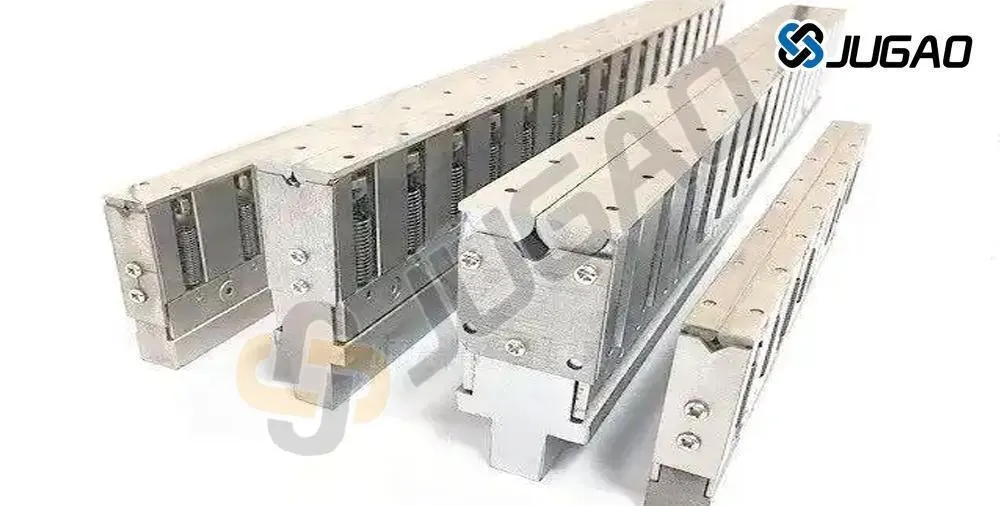
Electro-hydraulic press brake dies are specialized tools mounted on press brake machines to shape sheet metal through forming operations. Composed of multiple components that vary by die type, these tools apply pressure to alter the physical state of the material, transforming flat blanks into products with precise geometries and dimensions.
During installation, be sure to carefully check the equipment's condition to ensure safety during commissioning. By following the professional guidance of the press brake mold manufacturer, you can ensure safe use and processing results.
The following procedures outline the key steps for proper installation and adjustment.
1. Machine Preparation
Before installing the die, familiarize yourself with the machine’s operational parameters. Power on the system and conduct a thorough inspection to remove any residual debris, such as metal scraps or dust from prior operations. This preliminary check helps prevent operational issues and ensures a clean working environment.
2. Slide Stroke Adjustment
Begin by verifying the correct proportionality between the die thickness and the upper and lower die modules. The slide stroke should be calibrated to the transition point of the stroke curve. Incorrect adjustment at this stage may lead to die malfunction—a common yet avoidable error.
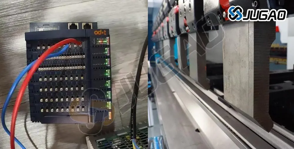
3. Stroke Module Setup
Once the slide stroke is properly configured, proceed to adjust the upper limit of the module. Set the module switch accurately when the module is at the top of its stroke. This allows hydraulic flow to initiate from the correct stopping position, enhancing operational efficiency. Additionally, implement deceleration settings as the module approaches bottom dead center to minimize impact and protect both the machine and the die.
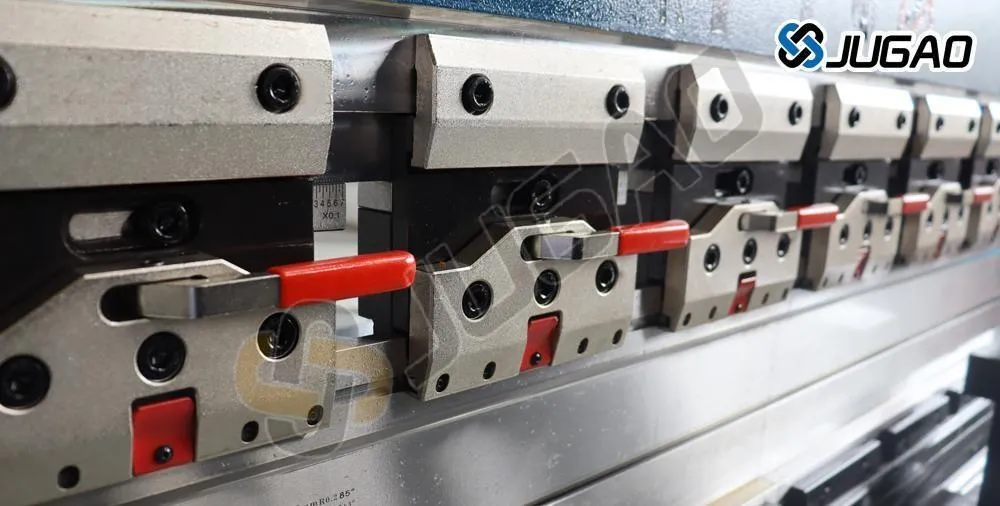
4. Die Clearance Adjustment
Measure and adjust the gap between the upper and lower dies according to the thickness and type of material being bent. The optimal clearance is determined based on the specific bending requirements and must be consistently maintained to ensure forming accuracy and tool longevity.
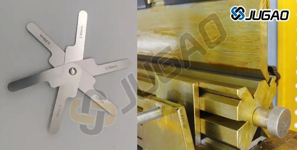
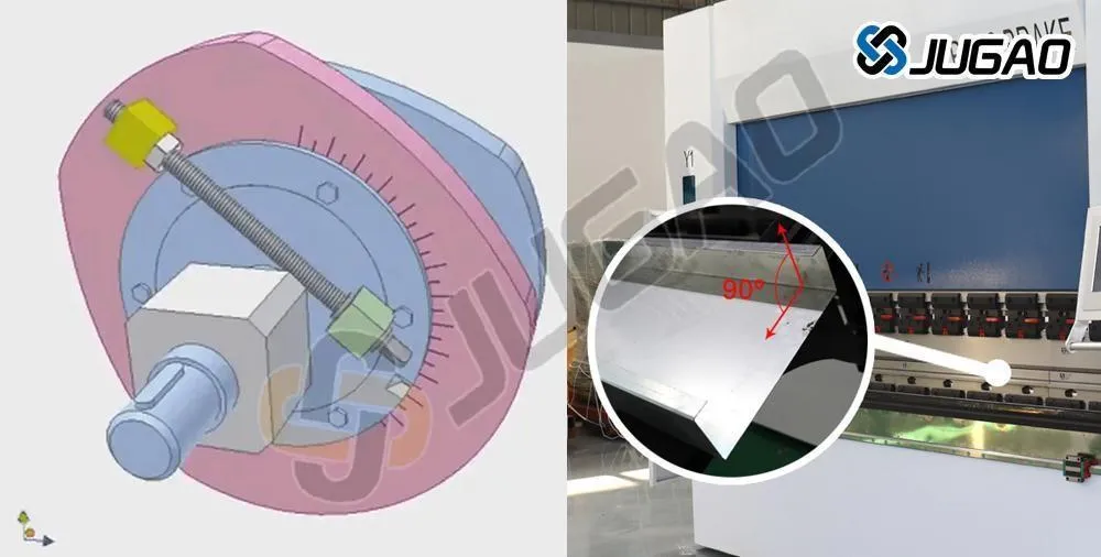
5. Bending Angle Calibration
The bending angle of the die must be aligned with product specifications. For instance, when forming a 90° bend, the central angle should be slightly larger than the angles at the sides. If the bend is too tight, fine-tune the machine’s adjustment screws to achieve the desired angle. Once set, avoid further changes unless there is a change in product requirements. During operation, use a pressure gauge to monitor and regulate bending pressure to prevent defects such as edge cracking or deformation.
![Smart equipment attracts global attention, and [Jugao Exhibition Hall] welcomes a wave of negotiations at the Canton Fair](https://shopsource.singoo.cc/1187/general/XTBdt5QeSjHYM3Rs/图片222.webp?x-oss-process=image/resize,w_100/quality,q_100)

Recent Posts

October 26, 2016
The Most Successful Engineering Contractor


![What Is Metal Plate Rolling Machine? [ Definition & Working Principle ]](https://shopsource.singoo.cc/1187/general/eJzA4YRePeWZisQ7/图片1.webp?x-oss-process=image/resize,w_100/quality,q_100)

Contact US
Product Information
Quantity
Unit
Piece
Support order samples, customization, wholesale direct, and complete payment. If the product you look for does not have corresponding customized content, pls fill out the form below to contact us, and we will reply ASAP.