- tel:+86-13222111178
- email:info@ntjugao.com


If your pipe bending machine controller malfunctions, don't rush to call the manufacturer. These methods can solve most problems.
If your pipe bending machine controller malfunctions, don't rush to call the manufacturer. These methods can solve most problems.

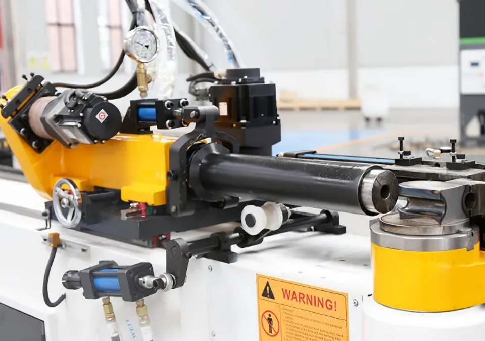
The controller is the brain of the human-machine interface, managing programming, logic, and communication. If it malfunctions, the entire machine becomes unresponsive. Follow these steps in order, and you can find the root cause of most controller problems.
Step 1: Check Alarms First, Then Determine the Direction
Most alarms on pipe bending machines are caused by external problems, such as an unreleased emergency stop, no sensor signal, or triggered limit switches. When an alarm light on the CNC system illuminates, the system maintenance manual usually provides a corresponding analysis path; checking it will quickly pinpoint the problem. Some systems have built-in diagnostic interfaces that allow you to view real-time data such as input/output status and servo load, helping you narrow down the possibilities.
Step 2: Restart – Always the First Method to Try
Controllers are like computers; memory crashes are common after prolonged use. Powering off the machine, waiting 20-30 seconds, and then powering it back on often resolves communication issues. If a system crashes, first check the controller panel lights: a constantly lit or flashing system fault light likely indicates a hardware or software problem; an off RUN light likely indicates a system shutdown.
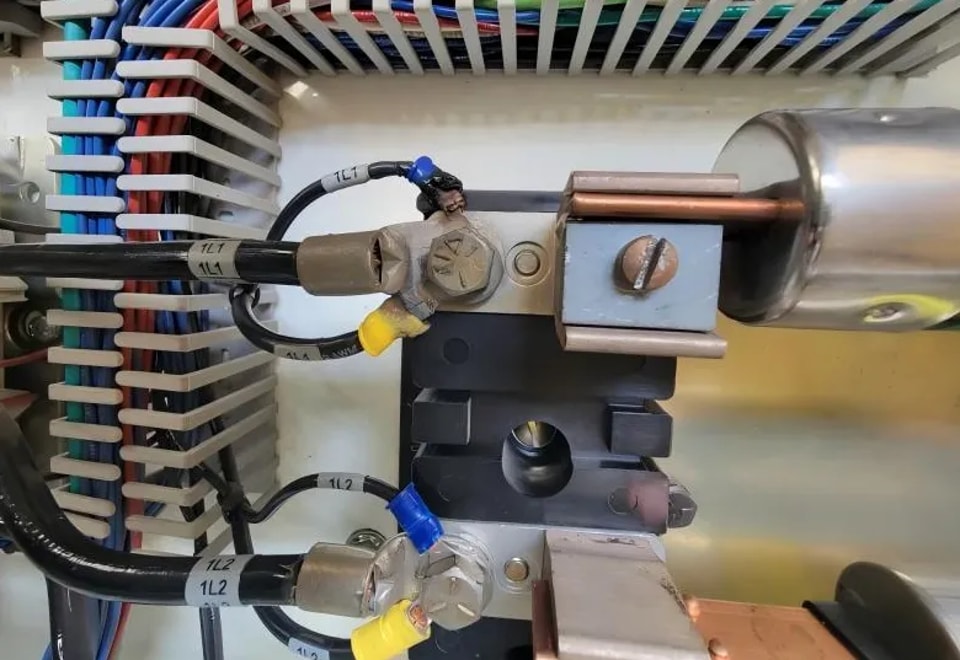
Step 3: Measure Voltage and Check Wiring
This is the most common cause of controller failure. Poor performance of the switching power supply is the root cause of many strange malfunctions. I once encountered a pipe bending machine that frequently overshot the bend; the problem was eventually discovered to be a degraded output filter capacitor in the 24V switching power supply. Connecting a 2200μF capacitor in parallel with the 24V output solved the problem. Therefore, when encountering difficult issues during debugging, first use a multimeter to measure the controller's power supply voltage; the 24V should be within ±10% for stability. If the power module shows signs of burning or the fuse is blown, replace it directly.
Additionally, industrial PCs are prone to crashing when operating in high-temperature environments for extended periods. First, check if the cooling fan is spinning and clean the dust from the heatsink to see if that helps.
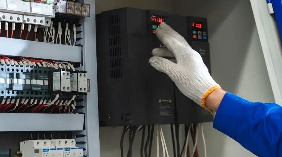
Step 4: Differentiating Between Controller Faults
Controllers are layered, requiring different troubleshooting approaches:
Industrial PC (IPC): If experiencing blue screens, crashes, or automatic restarts, first check the cooling system (CPU fan, chassis fan). After ruling out system software issues, use professional tools to check for hard drive bad sectors and memory errors.
Touchscreen/HMI:
Black screen, but normal screen surface temperature: The backlight circuit may be faulty. The filter capacitor on the high-voltage strip is the most prone to failure; try replacing it.
No power: Check the power adapter, power lines, and sockets.
No touch response: First, clean the screen of dust and oil, then check if the touch cable connection to the motherboard is loose.
PLC:
No input signal: Check the input detection page to see if the limit switches are functioning properly and if the wiring is broken.
No output: Check the output detection page to see if there is actual output. If there is output, check the wiring and switching valves; if there is no output, check the PLC logic or output module.
Communication Port/Bus:
If the network port indicator light is off, it's most likely a physical connection failure. Try replacing the cable or the port.
The station number, IP address, and baud rate must be consistent across protocols such as Modbus and Profinet. I've encountered communication interruptions due to IP conflicts after replacing equipment; changing the IP address resolved the issue.
Step 5: Check Program and Data Backup
If the program files are corrupted, simply overwrite them with backups. Incorrect parameter settings are a common software problem; restoring from a backup is the safest solution. Additionally, if the controller is connected to memory or a hard drive, you can remove and clean the oxide layer on the gold fingers to prevent poor contact and system crashes.
Step 6: Troubleshooting Special Issues
FSSB alarm on the driver side: This usually indicates a problem with the fiber optic line connecting the control card and the servo amplifier, or a problem with the amplifier itself. Check the fault code displayed on the 7-segment LEDs on the servo amplifier to immediately pinpoint the fault location.
Servo axis not moving: In manual mode, press the button on the non-active axis. Does the coordinate change? If the coordinate changes, check the driver settings and wiring.
Axis speed too high alarm: The speed parameter is set too high; adjust the speed value.
Limit switch alarm: Check if the positive and negative limit switches are sending signals. If the axis is pressed against the limit switch, move it in the opposite direction to release it. If it is not pressed, the problem may be a faulty limit switch.

Step 7: Develop Routine Maintenance Habits
Regularly use the accompanying software (such as Siemens' TIA Portal) to check the fault logs in the diagnostic buffer online. Focus on checking for red error entries, such as "division by zero" or "array out of bounds" errors, as these software errors can directly cause system crashes.
If the industrial PC or PLC crashes frequently after updating or modifying parameters, try reverting to a previous stable program version.
If frequent problems occur after long-term operation, check if the system is missing error handling code. Adding the corresponding code block should resolve the issue.
Keep the electrical cabinet dry and well-ventilated. Check the cooling fans and clean any accumulated dust.
Regularly monitor and analyze servo load, spindle load, and other data, and record any recurring alarms.
Controller malfunctions are essentially electrical faults, and most problems ultimately point to power supply, wiring, or signal interference. First, thoroughly check the peripheral components before suspecting the core circuit board. If all of the above fail, take pictures of the fault codes and symptoms and contact the manufacturer's technical support. Many major brands now support remote diagnostics, which is much faster than sending someone to the site.
Contact Us