- tel:+86-13222111178
- email:info@ntjugao.com


How to Resolve Angle Compensation Failure in CNC Press Brakes
How to Resolve Angle Compensation Failure in CNC Press Brakes

Table of Contents
• Fundamentals of Press Brake Angle Compensation
○ The Importance of Angle Compensation for CNC Press Brakes
• Primary Causes of Angle Compensation Failure in Press Brakes
○ Improper Crowning Parameter Configuration
○ Faults in Hydraulic Crowning Systems
○ Wear of Mechanical Crowning Components
• Systematic Troubleshooting for Angle Compensation Failure
○ Step 1: Confirm Tooling and Workpiece Installation
○ Step 2: Review CNC Controller Compensation Parameters
○ Step 3: Examine Hydraulic or Mechanical Compensation Units
○ Step 4: Conduct Test Bending and Angle Verification
• Proactive Measures to Avoid Angle Compensation Failure
○ Regular Calibration of Crowning Systems
○ Routine Maintenance of Hydraulic Parts
○ Standardized Tooling Upkeep
• Frequently Asked Questions
○ What is the most frequent trigger of press brake angle compensation failure?
○ How to rapidly test the functionality of a press brake compensation system?
○ Can worn tooling lead to angle compensation failure?
○ How frequently should the press brake crowning system be calibrated?
• Conclusion
When operators face inconsistent bending angles during production, the first component to inspect is typically the press brake angle compensation system, as failure in this unit is a common culprit. Angle compensation is vital for sustaining bending precision, particularly when processing lengthy or thick metal sheets. A malfunctioning compensation system will result in varying angles across a single workpiece, triggering quality defects and material waste. This guide elaborates on the typical causes of press brake angle compensation failure and provides practical, step-by-step troubleshooting methods to diagnose and resolve the issue efficiently.
Fundamentals of Press Brake Angle Compensation
Before addressing the failure, it is essential for operators to grasp the working principle of the angle compensation system, commonly known as crowning compensation. This system is designed to offset the inherent deflection of the machine frame during the bending process.
The Importance of Angle Compensation for CNC Press Brakes
During metal bending, the central sections of the ram and bed experience slight deflection under applied pressure. Without effective compensation, the bending angle at the workpiece center will deviate from those at the two edges. The angle compensation system rectifies this deflection to ensure uniform bending across the entire workpiece.
Modern CNC press brakes commonly adopt three types of compensation systems:
• Mechanical crowning systems
• Hydraulic crowning systems
• CNC-driven automatic compensation systems
Failure of any core component in these systems will lead to angle compensation failure, manifesting as inconsistent bending angles.
Primary Causes of Angle Compensation Failure in Press Brakes
When troubleshooting bending angle anomalies, focus on the following typical causes:
Improper Crowning Parameter Configuration
Incorrect parameter settings in the CNC controller are the leading cause of compensation failure. If the set crowning value fails to match material thickness, die opening size, or bending force, the system cannot perform effective compensation.
To fix this issue:
• Check the crowning parameter values in the CNC controller
• Verify the accuracy of input material thickness and die width
• Adjust the compensation value based on actual bending tonnage
Correcting these parameters often resolves the compensation failure immediately.
Faults in Hydraulic Crowning Systems
For press brakes equipped with hydraulic crowning units, hydraulic pressure is a critical factor. Abnormal operation of the hydraulic system will directly cause compensation failure.
Typical symptoms include:
• Uneven bending angles along the workpiece
• Slow or lagged compensation response
• Fluctuating hydraulic pressure
Inspect hydraulic valves, pressure sensors, and oil flow to ensure the normal operation of crowning cylinders.
Wear of Mechanical Crowning Components
Mechanical crowning systems rely on adjustable wedges or blocks installed beneath the lower table. Prolonged use may cause these parts to wear or misalign.
Inspection items include:
• Alignment of wedge blocks
• Lubrication status
• Precision of mechanical adjustment
Cleaning and recalibrating the mechanical crowning unit can usually restore normal compensation function.
Systematic Troubleshooting for Angle Compensation Failure
Adopt a structured troubleshooting process in workshop operations to locate the root cause quickly.
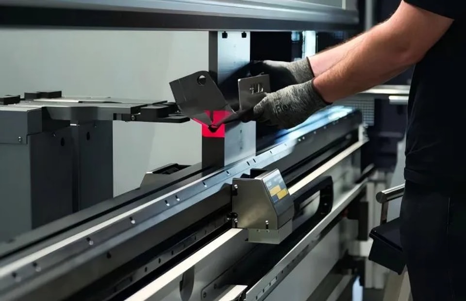
Step 1: Confirm Tooling and Workpiece Installation
Prior to checking the machine system, verify the correctness of tooling setup first, as improper setup can mimic compensation failure.
Key inspection points:
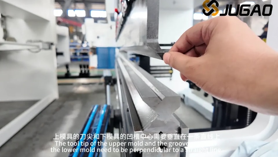
• Alignment between punch and die
• Wear or damage to tooling surfaces
• Matching of die opening size with processed material
Step 2: Review CNC Controller Compensation Parameters
Next, check and adjust the parameter settings in the CNC controller.
Core parameters to verify:
• Crowning compensation value
• Bending force calculation logic
• Input material performance parameters
• Sheet thickness data
Inaccurate input data will lead to wrong compensation calculations.
Step 3: Examine Hydraulic or Mechanical Compensation Units
Conduct targeted inspections based on the press brake’s compensation structure:
• For hydraulic systems: Check oil pressure stability, hydraulic valve functionality, and movement of compensation cylinders
• For mechanical systems: Verify wedge block movement, lubrication condition, and mechanical calibration accuracy
These inspections will generally identify the fundamental cause of compensation failure.
Step 4: Conduct Test Bending and Angle Verification
After completing adjustments, perform a test bending operation. Use a digital angle gauge to measure angles at three positions:
• Left end of the workpiece
• Central section
• Right end
Consistent angle readings across all positions confirm the compensation system is functioning properly.
Proactive Measures to Avoid Angle Compensation Failure
Preventive maintenance can greatly reduce the occurrence of angle compensation issues in daily production.
Regular Calibration of Crowning Systems
Periodic calibration guarantees the long-term accuracy of the compensation system. It is recommended to verify crowning parameters after major tooling replacements or material switches.
Routine Maintenance of Hydraulic Parts
For hydraulic crowning systems, routine maintenance includes:
• Checking the quality and level of hydraulic oil
• Monitoring pressure stability
• Cleaning or replacing hydraulic filters
These steps prevent performance degradation of the hydraulic system.
Standardized Tooling Upkeep
Tooling condition directly impacts bending accuracy. Keeping punches and dies clean, intact, and properly aligned reduces compensation errors and enhances production consistency.
Frequently Asked Questions
What is the most frequent trigger of press brake angle compensation failure?
The most common causes are incorrect CNC parameter settings, hydraulic crowning system malfunctions, and mechanical crowning block misalignment.
How to rapidly test the functionality of a press brake compensation system?
Perform a test bend and measure angles at multiple positions along the workpiece. A noticeable difference between the center angle and edge angles indicates potential compensation malfunction.
Can worn tooling lead to angle compensation failure?
Yes. Worn or damaged punches and dies can produce uneven bending angles, which are easily mistaken for compensation system failure.
How frequently should the press brake crowning system be calibrated?
Calibration is recommended when replacing tooling, processing new materials, or detecting bending accuracy deviations.
Conclusion
Press brake angle compensation failure severely compromises bending precision, production efficiency, and product quality. By understanding the operating principle of the compensation system and following a structured troubleshooting flow—verifying tooling setup, checking CNC parameters, and inspecting compensation hardware—most failures can be diagnosed and fixed promptly.
Regular preventive maintenance and standardized machine calibration are the most effective ways to prevent such failures. If bending accuracy issues persist or professional technical support is needed for the press brake system, contact the technical team or refer to advanced maintenance guides on the official website.
Contact Us