- tel:+86-13222111178
- email:info@ntjugao.com


Executing a Program on the ESA S860: A Step-by-Step Guide
Executing a Program on the ESA S860: A Step-by-Step Guide

This guide provides a clear, step-by-step methodology for efficiently executing programs on the ESA S860 system. You will learn the essential procedures for entering and running both numeric and graphic programs—a core competency for achieving precision in metal fabrication. Furthermore, we will cover how to master the bending sequence, from automated execution to manual adjustments, enabling you to significantly optimize workflow, reduce setup time, and maximize overall productivity.
List of Programmes
To enter the list of programmes in the Programme in ESA S860, it is necessary to follow the steps below:
– press
– the following window will appear:
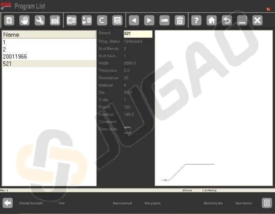
In the Programme in ESA S860, the left window is the list window, with central boxes displaying the programme data highlighted by the cursor. The right window provides a preview of the punch corresponding to the cursor’s position. Use your finger to scroll through the available programmes, simplifying the search and execution process.
l Function Keys Overview:
² [Directly in Automatic]: Enable this to execute a programme in ESA S860 directly without editing. A red square next to DirectAuto indicates the selection.
² [Search]: Quickly find a specific programme to execute by using this function.
² [New Numeric]: Create a new numeric programme for immediate execution.
² [New Graphic]: Set up a new graphic programme for subsequent execution.
² [Save Version]: Save your programmes in a previous version for easy retrieval and execution.
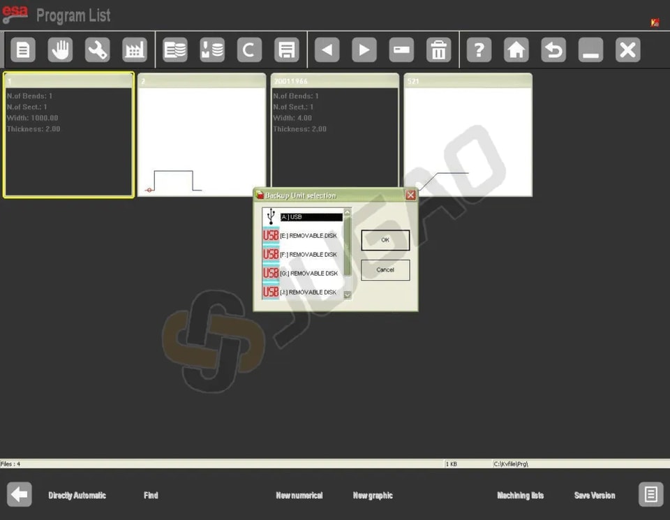
View Programme List on USB
l Insert USB containing programmes into the port.
l Press the designated key to display the programme list.
l You can copy, rename, or delete programmes like you do with the tool list.
Changing the Work Unit
l Open the Programme list by pressing the key.
l Press another key to access the menu.
l Select ‘7 »Backup unit’ to change the work unit.
Entering Programmes in ESA S860
Accurately entering programmes in the ESA S860 system guarantees that the end results meet the desired specifications. Here’s how you can execute a programme in ESA S860 effectively.
Entering a Numeric Programme
Step 1: Navigate to Programme Entry Mode
To enter a new numeric programme it is necessary to:
– press
The Home mask will open:
On the mask it is chosen [New prog. of bend] pressing![]()
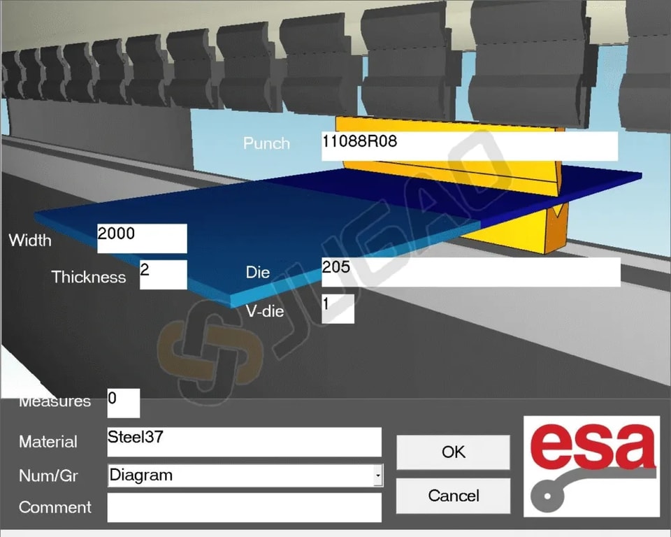
Step 2: Input Data Precisely
A window will open for entering the programme data. Please note that the touch mode provides the scroll:
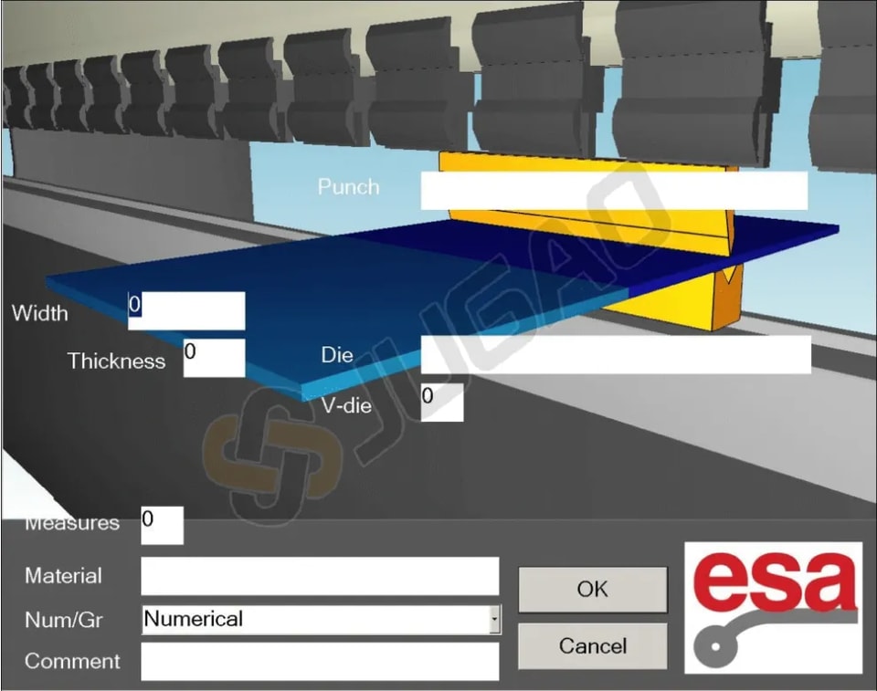
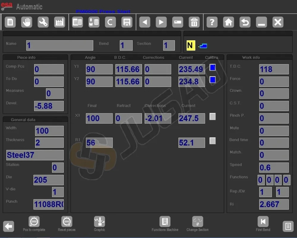
1. Choose the Punch: Click to open the Punch List and select your pre-drawn punch with a double-click or double-touch.
2. Select the Die: In the program editor, choose your pre-drawn die. Both selections will appear in the programme.
3. Enter Die Cavity: Input the die cavity number; enter “1” if there is only one cavity.
4. Specify Metal Sheet Dimensions: Enter the width and thickness of the sheet.
5. Select Material: Use the Materials Table to quickly choose the material and its resistance.
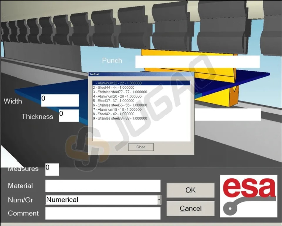
After selecting material appears in what is described in the NAME field of the table material.
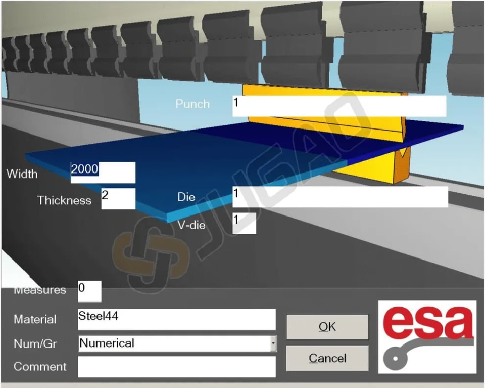
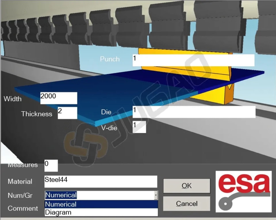
Set specifying that the programme is numeric in the field Num / Gr.
To accept the data, to press [Confirm], allowing the direct access the Settings mask.
![]()
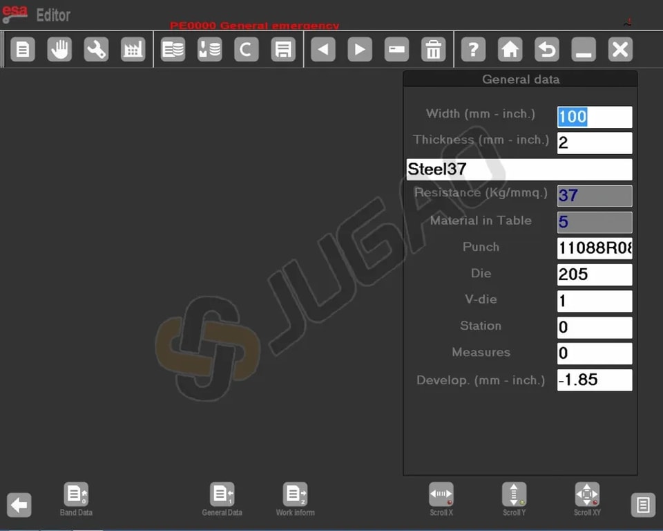
From the Setting mask by pressing this fuction key, you enter the General Data mask.
![]() Also from the Settings mask by pressing this function key, you enter the Work Data mask:
Also from the Settings mask by pressing this function key, you enter the Work Data mask:
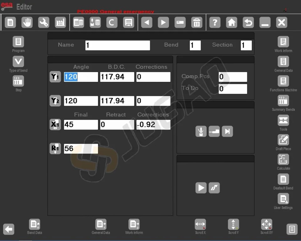
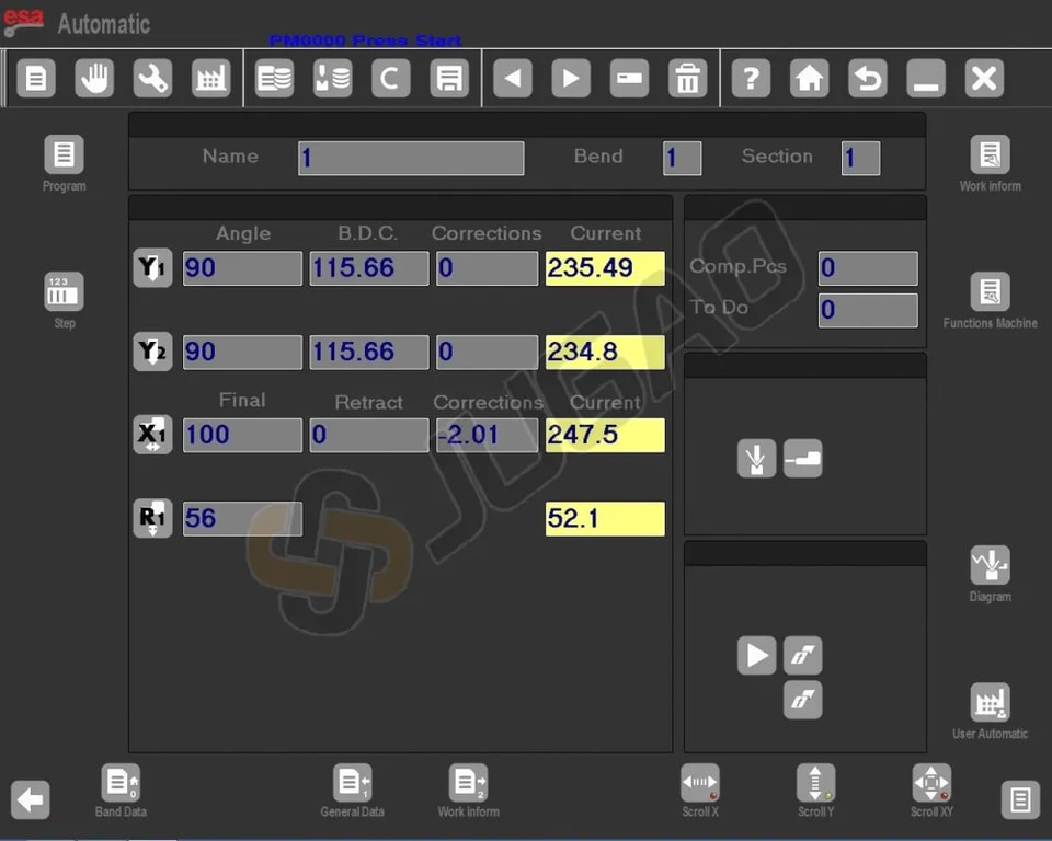
Setting the Bends
1. Set Bend Angles: Move the cursor to the Y1 angle field and enter the desired bend angle.
2. Set Bend Lengths: Enter the required bend length in the Field Finali X1.
3. Automatic Calculations: Other bend-related data will be calculated automatically, but you can modify these as needed.
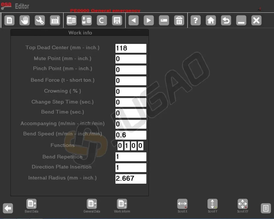
Viewing Work Data
-Press this key.![]() A window will display essential data like P.M.S, P.C.V, and P.C.L for the bend.
A window will display essential data like P.M.S, P.C.V, and P.C.L for the bend.
Managing Bends
1. Copy a Bend: Navigate to the desired bend, open the menu, and select Copy Step to replicate the bend at the end of the section.
2. Enter a Bend: Move to the position after the desired insertion point, open the menu, and select Enter Step.
3. Enter a Copied Bend: Similar to entering a bend but after copying, use Copy Step again for precise placement and duplication.
Defining Calendering
4. Activate Calendering: Open the menu, select the [Calendering] function.
5. Input Data: Enter angle, radius, pitch length, and initial stop position.
Defining Clinching (Bend and Squash)
Enter 0.0 in the Y1 angle field; the ram’s arrival value will consider cavity depth and thickness. For ensuring greater work programming speed a clinching can be defined by directly entering the setting mask.
– Press this key to open the menu![]()
– Press the Clinching function key![]()
Clinching Correction
-Enter the Corrections mask by pressing
-Increase value if bend is too squashed. Adjust Height Y2 afterwards.
-Alter P.M.I. using [Correction coefficient]. Cancel with [Ignore correction].
Coining or Moulding Operations
For ensuring greater work programming speed it is possible to carry out a coining or moulding operation simply:
-Press this key to open the menu![]()
-Select the Coining Function key![]()
Coining Correction
Adjust Lower Dead Point: Reduce if shallow, increase if deep. Use [Correction coefficient] if needed.
Conical Bend Definition
-Ensure the X2 axis is configured for conical operation and mounted correctly, either incrementally on the X1 bar or as independent axes.
-Enter initial stop position in X1. Use the conical function key![]()
, input the desired angle (-45 to 45 degrees), and confirm.
-Positive angles adjust X2, Z1, Z2; negative affect X1, Z1, Z2. Re-enter new bends if adjustments are made.
Out-of-Cavity Bends
1. Direct Input: Enter end bend values in P.M.I Y1 and P.M.I Y2.
2. Programme Adjustments: Ensure P.C.L and P.C.V fields reflect values exceeding theoretical end heights.
3. Height Validation: Maintain proper height order for automatic programme execution.
Entering a Graphic Programme
Step 1: Select Graphic Entry Option
In the programme data screen, choose “Graph” under Num/Gr.
To execute a programme in ESA S860, begin by entering the sheet width and thickness, select the material from the Materials Table, then specify work station, die details, cavity orientation, and punch details, along with any optional comments.
Step 2: Utilize Design Tools
With the Soft Keyboard you can:
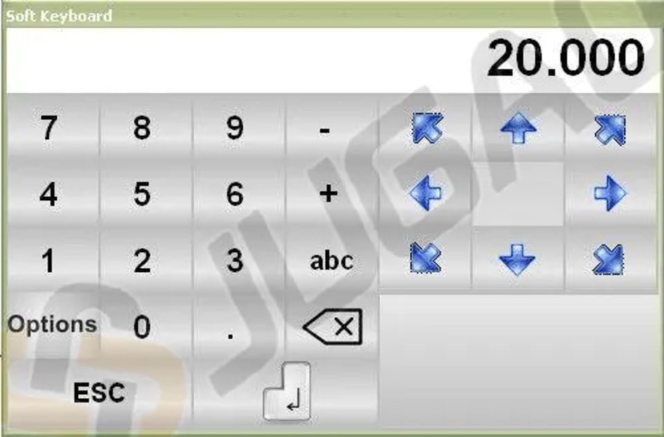
l Adjust Segment Length: Change the first segment’s length by entering a new height, confirm, and select a BLUE arrow to auto-display the next bend angles.
l Set Segment Angle: Use the seven arrows (45, 90, 135, 180, -135, -90, -45) to set angles quickly.
l Manual Angle Input: If “pincushion” is off, tap the ALPHA field to input angles manually.
l Input Length and Angle: Tap the line’s centre to input length or press intersections.
l Zoom and View Adjustments: Use the ZOOM bar to scale and move the view for better visualization
l Navigate with CALCULATE: Press CALCULATE and drag the machine drawing to adjust its position, improving planning in SEMIAUTOMATIC and AUTOMATIC modes of ESA S860.
How to carry out the drawing of a piece
Let’s suppose we have to draw the piece illustrated in the figure below:
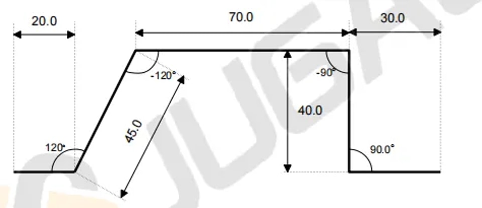
1. Start Drawing Mode: Place the cursor in Field l for polar setting.
2. First Section:
² Enter length (20.0) in Field l.
² Enter angle (120.0°) in Field α.
3. Second Section:
² Enter length (45.0) in Field l.
² Enter angle (-120.0°) in Field α.
4. Third Section:
² Enter length (70.0) in Field l.
² Enter angle (-90.0°) in Field α.
5. Fourth Section:
² Enter length (20.0) in Field l.
² Enter angle (90.0°) in Field α.
6. Fifth Section: Enter length (30.0) in Field l, press [ENTER] to complete.
Bending Sequence Calculation
For optimal results, calculating the bending sequence in the Programme in ESA S860 is crucial.
Automatic Calculation of the Bending Sequence
A Programme in ESA S860 can automatically calculate the bending sequence, optimizing bend order for enhanced efficiency. Simply enable ‘Automatic Bending Calculation’ in the settings to allow the system to compute the best sequence for your bends.
Manual Calculation of the Bending Sequence
When using a programme in ESA S860, manual intervention may sometimes be necessary. Manually calculate the bending sequence using the manual guide, then enter your sequence into the system to ensure accurate adjustments. This approach enhances flexibility and precision within your programme in ESA S860.
How to Bend a Box
1. Create Two Sections: Horizontal bends and vertical bends, in either graphic or numeric mode.
2. Execute Sequentially: Begin with the section with the smallest sheet width to ensure precision.
3. Adding/Deleting Sections:
² To add, press [Change Section].
² To delete, open the menu and select ‘Delete Section’. This will reset to bend 1 of section 1.
Execute a Programme in ESA S860
Executing in Automatic Mode
 Initiate by pressing this key after setting a numeric or graphic programme in ESA S860.
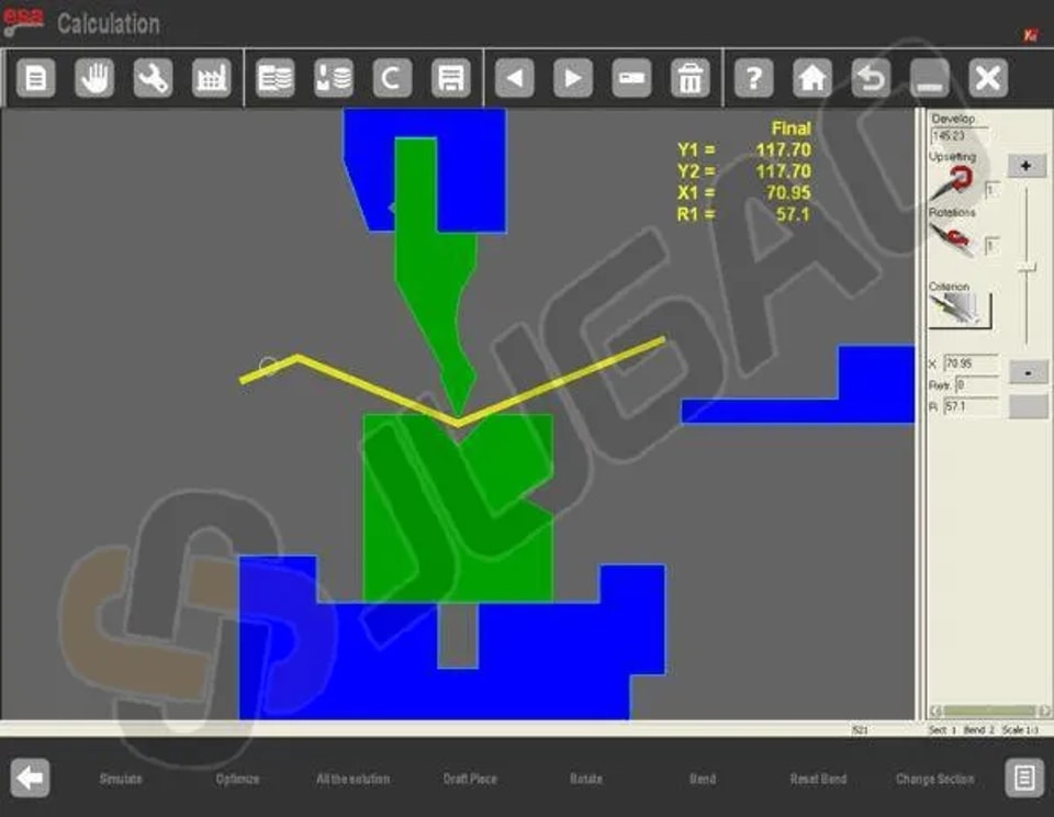
Automatic Graphic Mask
Press [Graphic] to view the mask for a calculated graphic programme.
l Main Window: Shows machine parts, punch, die, and piece before/after the bend.
l Orientation Guidance: Offers instructions on sheet clinching or rotation during bends.
l Data Display: Bend details and piece counter, with axis heights shown in yellow.
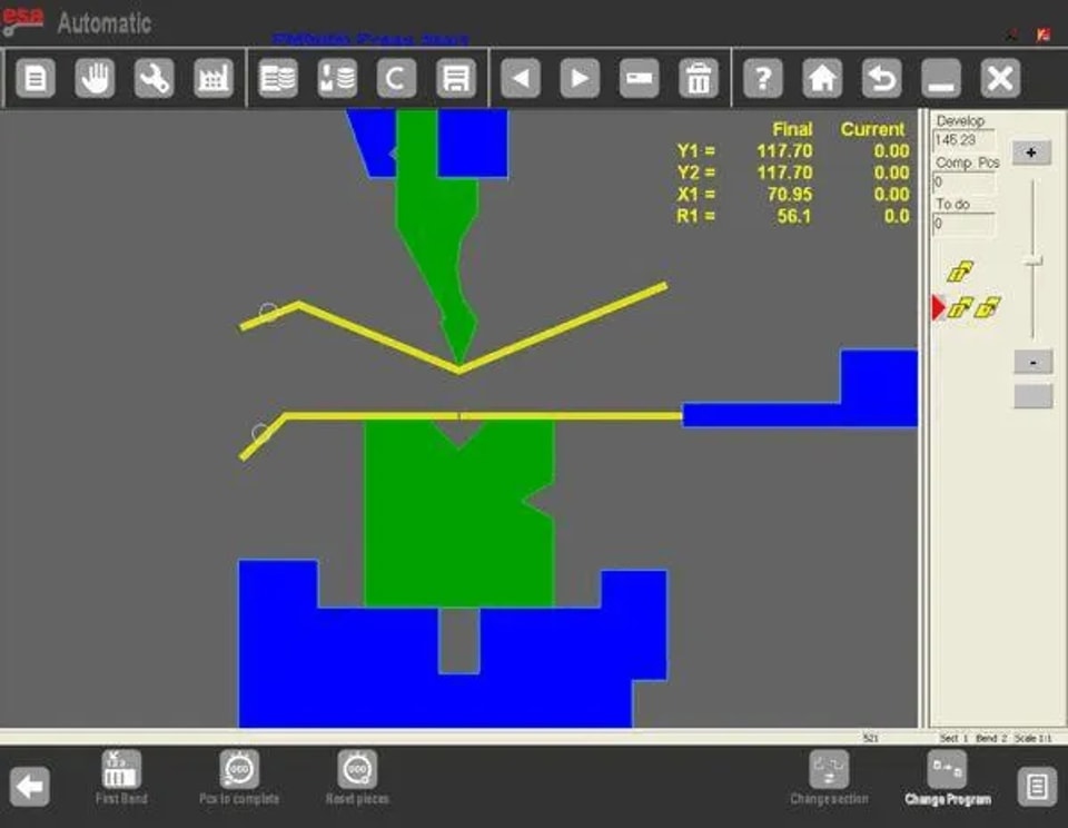
Automatic Numeric Mask
l Axis Heights Display: Shows current axis heights; changes not allowed in automatic mode.
l Piece Orientation: Provides guidance for each bend, such as clinching or rotation.
l Display Size Toggle:
² Press for double size, similar to Kvara S 860 PC and S 660W.
² Press again for single size.
Conclusion
In summary, running a program on the ESA S860 requires effective use of several essential functions. Key steps include correctly displaying current axis heights in automatic numeric mode, following precise instructions for part orientation during bending operations, and switching between display sizes as needed for ease of use.
Should you require further technical support or have additional questions, our team is readily available to assist. We also encourage you to explore our comprehensive documentation to gain deeper insights and fully leverage the potential of your ESA S860 system.
Contact Us