-
tel:
+86-13222111178 -
email:
info@ntjugao.com


Elevating Design with ESA S630 Integrated CAD
Elevating Design with ESA S630 Integrated CAD
Dec 19, 2025
When it comes to advancing design performance, the ESA S630 Integrated CAD system distinguishes itself as a robust solution for designers and engineers. If you're interested in understanding how this integrated CAD platform can optimize your design workflow, you’ve come to the right resource.
In this article, we will explore the distinctive functionalities of the ESA S630 Integrated CAD and demonstrate how it enhances process efficiency and design accuracy. Whether you are new to CAD software or seeking to improve your existing setup, this guide offers practical insights for leveraging the ESA S630 to achieve superior design results.
Introduction
The ESA S630 Integrated CAD system delivers advanced capabilities that significantly improve design workflows, especially in metalworking applications involving press brakes. A key strength of the system is its ability to generate critical graphic components—such as the upper and lower sections of the machine, the punch, the die, and the workpiece to be bent. This integrated approach enables designers to validate bending sequences with precision, reducing the likelihood of errors and accelerating production processes. The accompanying user guide offers straightforward access to these drafting tools, helping users fully exploit the ESA S630’s potential for greater design reliability and productivity.
Drawing Function
The drawing function within ESA S630 Integrated CAD greatly simplifies and expedites the early phases of design. By enabling line segments to be automatically generated from operator-input data, this tool boosts both the speed and precision of drafting. The system accommodates data entry in both polar and Cartesian formats, with polar format generally recommended for its ease of use. This adaptability promotes accuracy while minimizing input mistakes, establishing the drawing function as a vital asset for efficient and error-resistant design development.
Polar Setting of the Drawing Data
The polar coordinate setting in ESA S630 Integrated CAD plays a critical role in improving design precision, especially in intricate projects. This feature allows drawing segments to be defined by length and angle—within a ±180.0° range—guaranteeing exact orientation and placement. It is especially advantageous in applications that demand rigorous dimensional control, such as architectural planning and mechanical engineering.
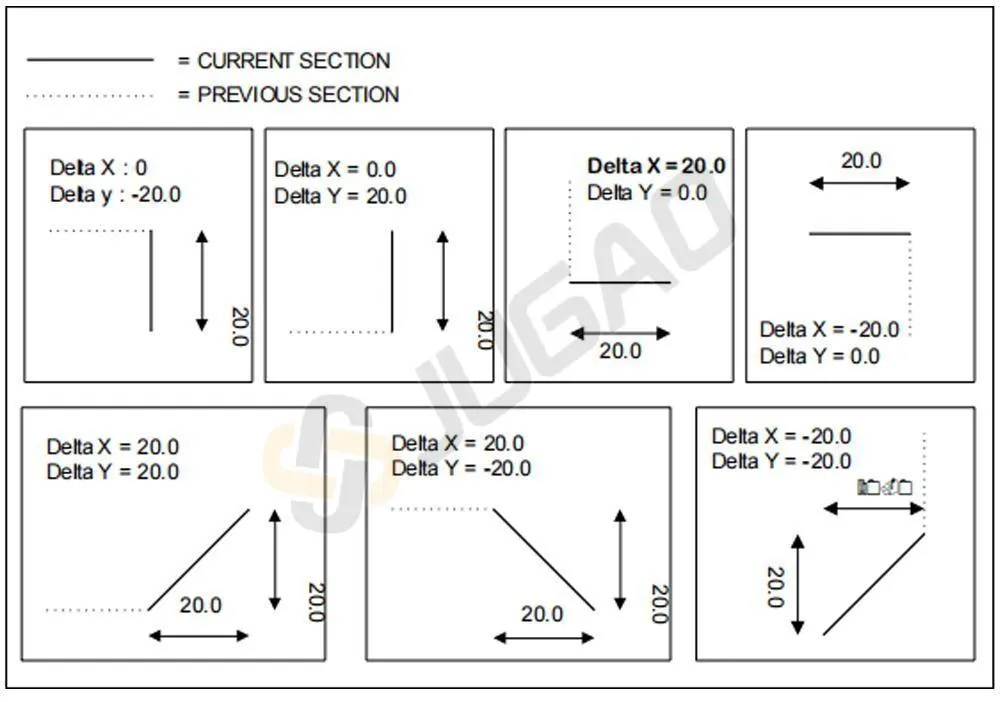
The conventions for entering these angles are as follows:

Cartesian setting of the drawing data
This function allows for defining the sections that will make up the drawing by means of a pair of coordinates that identify the difference between the beginning and end of the segment.
The Cartesian coordinates are not absolute but instead relate to the beginning of the segment and they must be entered.
General data
Before starting the drawing of a graphic element it is necessary to enter some general data that will vary according to the object you wish to draw.
The data to be introduced in this phase are described in the specific chapters for each object.
Drawing Page
The drawing page within ESA S630 Integrated CAD is a cornerstone of its user-friendly design, crafted to enhance organization and accessibility of design data seamlessly. To access the drawing interface, simply select the [Ok] button with your finger—this intuitive access is just the beginning of the thoughtful design.
The drawing page is structured into several distinct areas:
l Area 1: Drawing Information or Status Bar: This window displays essential details such as the name of the program you are working on, the section and step number of the current drawing, and the scale factor. This real-time information ensures you are always aware of the specifics of your design process.
l Area 2: Graphic Tracing Window: Here, the graphic representation of your drawing comes to life based on the data entered. It serves as the visual hub where your designs take shape, providing an immediate reflection of your inputs.
l Area 3: Polar Setting Window: This area allows for precise data entry related to the length of the side to be drawn (‘l’) and the angle (‘Alpha’) compared to the following side. The polar setting enhances the precision and flexibility required for complex designs.
l Area 4: Cartesian Setting Window: In this window, you can input Cartesian coordinates (‘DX’ and ‘DY’). These coordinates reflect the difference between initial and final coordinates of the length to be drawn, adding another layer of accuracy to your design.
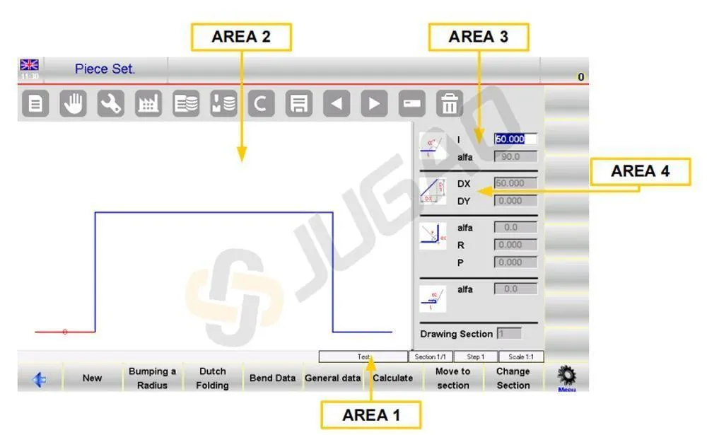
The thoughtfully organized windows not only streamline the drawing process but also significantly improve the accessibility and management of design data. With the ESA S630 Integrated CAD drawing page, designers have a comprehensive and intuitive interface that supports efficient and precise design development.
Entering of the Data of the Drawing
Entering data accurately and efficiently is a critical aspect of creating precise designs, and ESA S630 Integrated CAD excels in this area with its intuitive data entry functionalities. When you first access a drawing in Area 2, the first side standard length is automatically drawn and highlighted in red, allowing you to easily verify and adjust initial settings. The initial direction can be swiftly altered by accessing the [Sub Menu] and selecting [Rotation], ensuring flexibility in your design process.
How to enter a drawing in polar mode
If the cursor is not located in the field “l” of Area 3 it will be necessary to press the button [Sub Menu] and [Polar Format] to activate the polar type setting. The values to be entered are as follows:
l The length of the side; the side will be rescaled depending on the length entered and the cursor will move onto the “alpha” Field for setting of the angle.
l The angle compared to the following length.
The length described above will turn blue; the following length will be drawn, it becomes the current length, it will be shown in red. A circle surrounds the section currently being entered.
After completing the entering of the data the cursor moves into field for setting the length of the new side. The entering of this data pair must be repeated until the drawing has been completed.
Updating the information about the drawing
If the measurements entered exceed the dimensions of the window, the drawing will automatically be rescaled; the scale factor of the drawing in Area 1 will be updated.
Every time a new length is drawn the number of the current length is displayed in the “step” Field of the Area 1 it will be increased.
Finish the drawing
In order to indicate that the drawing is finished you must set the angle of the last length to zero.
How to select the drawing data
To select the drawing data it is necessary to scroll through them with these two buttons


The button scrolls backwards through the data forming the drawing in sequential mode, passing step-by-step between the “alpha” and the “l” Field. The scrolls forwards through the data in sequential mode, passing step-by-step in the “l” Field. When you scroll through the data of a drawing the length relating to the data displayed will be highlighted and the number of the current step will be displayed in the Area 1.
Change the drawing data
To change the drawing data it is necessary to:
· select the value.
· enter the new value.
· press [Ok] to accept the new value.
· the drawing will be traced depending on the new value entered.
Use of the directional arrows of the soft keyboard

The directional keys move horizontally or vertically the length.
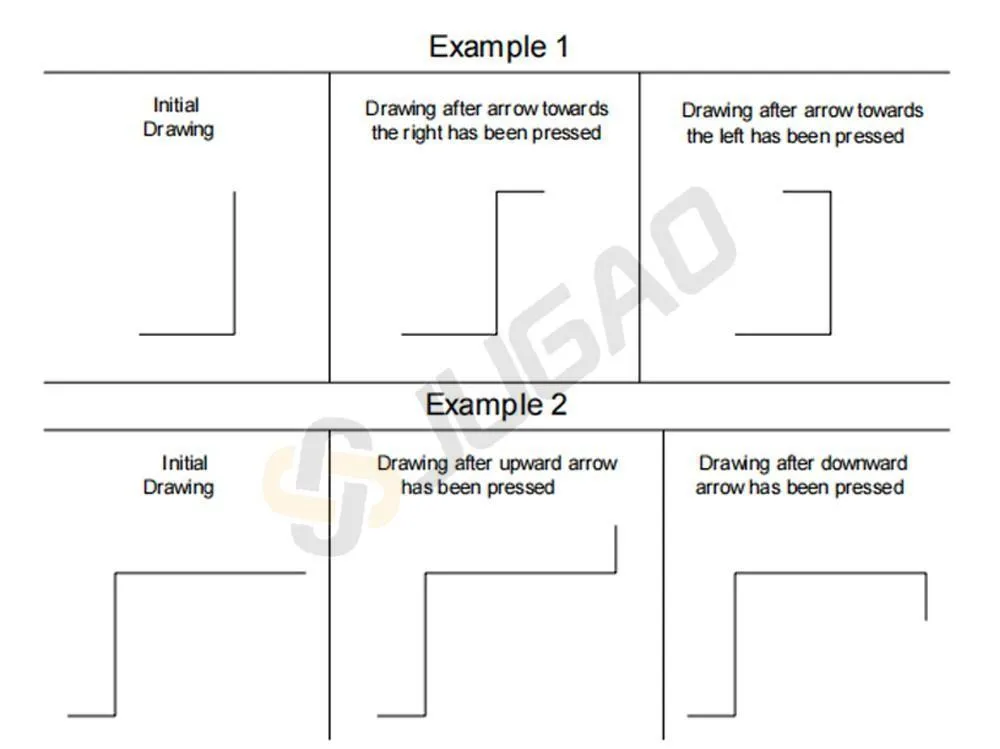
Using the directional arrows and keys of an external keyboard
In our CNC is it possible connect a ps2 or USB external keyboard.
The directional keys move diagonally through the segments.

The existing angle is automatically entered in the “alpha” Field between the current length and the side traced depending on the directional key that has been pressed.
How to delete a length of the drawing
With ESA S630 Integrated CAD, deleting a length involves selecting the desired section and pressing a button. The deleted length adjusts the following length based on the previous angle.
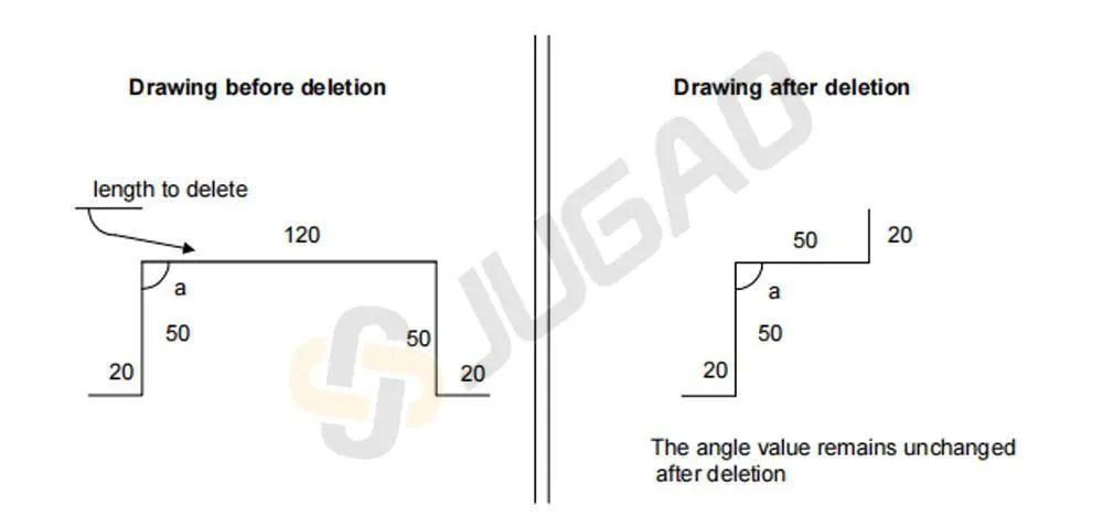
If the last length is removed, it defaults to a standard length. To delete the final length, navigate to the prior data before completing the drawing.
How to enter a length in the drawing
Inserting a new length is straightforward with ESA S630 Integrated CAD. By pressing the appropriate button and selecting “1>> Insert,” you can add a length before the current one. The newly inserted length will initially be standard, effectively extending the current length by 20 mm. To achieve your desired drawing specifications, simply input the necessary values for the new length.

If you encounter any challenges using the Insert function, a practical approach is to navigate to the insertion point, delete all subsequent lengths, and redo the drawing.
How to use the Cartesian format
To enhance your design workflow with ESA S630 Integrated CAD, effectively using Cartesian format is crucial. When polar format isn’t feasible, ESA S630 Integrated CAD allows you to define segments in Cartesian format.
Simply press [Sub Menu] and then [Cartesian Editor] at your desired drawing length. In Area 4, enter the horizontal difference in the DX field and the vertical difference in the DY field, confirming each with [Ok].
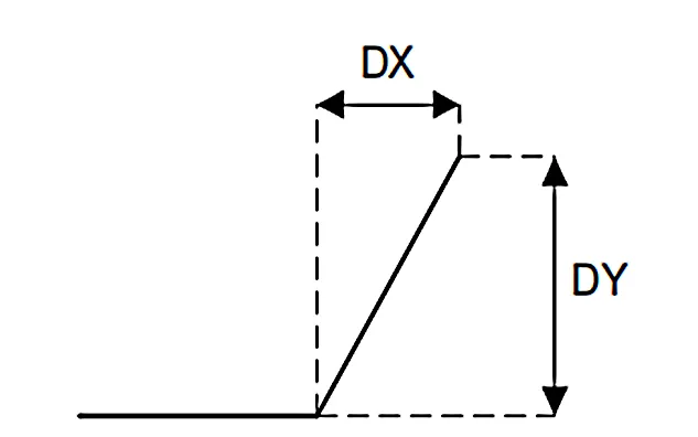
To switch back to polar format, press [Polar Editor]. This flexibility in ESA S630 Integrated CAD lets you efficiently adapt your designs, ensuring precision and optimizing your workflow.
Conclusion
In summary, the ESA S630 Integrated CAD system provides a comprehensive suite of powerful features that substantially elevate the design experience. By leveraging its advanced drawing capabilities, precise polar coordinate settings, user-friendly drawing interface, and streamlined data input methods, designers can optimize workflows, enhance accuracy, and achieve superior design outcomes. The integration of these key functionalities establishes the ESA S630 as an essential tool for contemporary design projects.
To further explore how ESA S630 Integrated CAD can enhance your design efficiency and precision, we invite you to discover additional resources available on our website. For specific inquiries or personalized guidance, our expert team remains readily available to provide support. We are committed to helping you unlock the full potential of your design workflows through the advanced capabilities of ESA S630 Integrated CAD.


Recent Posts

October 26, 2016
The Most Successful Engineering Contractor
Apr 16, 2026
Replacement Frequency of Welding Robot Contact Tips

Apr 16, 2026
Rotational Degrees of Freedom in Welding Robots


Contact US
Product Information
Quantity
Unit
Piece
Support order samples, customization, wholesale direct, and complete payment. If the product you look for does not have corresponding customized content, pls fill out the form below to contact us, and we will reply ASAP.