- tel:+86-13222111178
- email:info@ntjugao.com


A Practical Guide to Operating the E21 Press Brake
A Practical Guide to Operating the E21 Press Brake

To operate the E21 Press Brake, begin by entering the required bending parameters into the control system. Once the material is correctly positioned and secured, you can initiate the bending cycle, adhering to all standard safety protocols. For consistent, high-quality results, it is essential to perform routine maintenance and regular tool inspections.
For a detailed, step-by-step walkthrough of the entire process, proceed to the complete operational manual below.
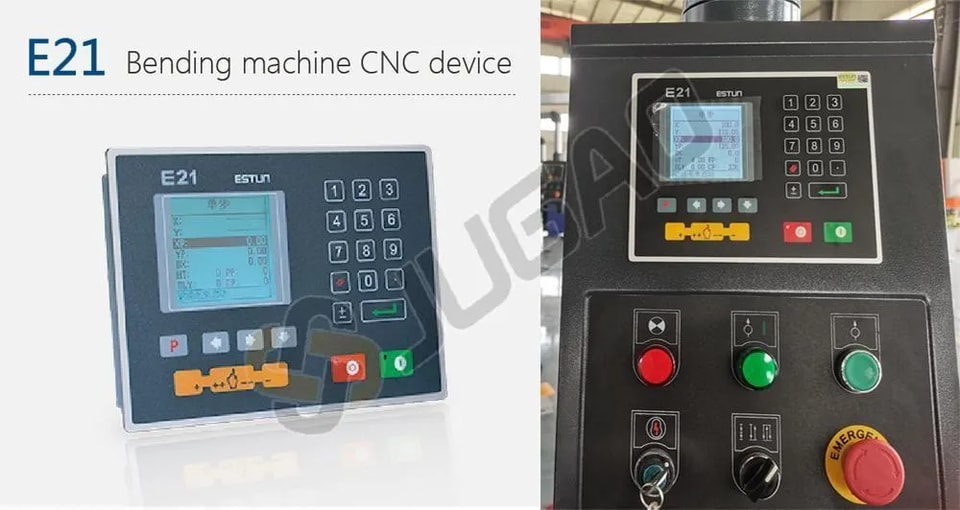
E21 System: An Introduction
The E21 is a specialized control system designed specifically for press brake machines. It delivers an optimal balance of performance and cost-efficiency, significantly reducing overall machine expenses while maintaining precision within required industrial standards.
Key features of the E21 system include:
l The high-definition LCD screen supports bilingual Chinese and English, and displays pro-gramming parameters on one page, making programming faster and more convenient.
l Intelligent positioning of X and Y axes supports manual adjustment, eliminating the needfor mechanical hand-operated positioning devices.
l Built-in pressure holding time and unloading delay setting functions make operationeasier and reduce costs.
l one-click parameter backup and recovery function, which can restore parameters at anytime as needed, reducing maintenance costs.Support multi-step programming to improve production efficiency and processing accu-raCy.
l All buttons on the panel are micro switches and have been strictly tested for EMC, highand low temperature, vibration, etc. to ensure the stability and service life of the product.
l CE certification support overseas markets.
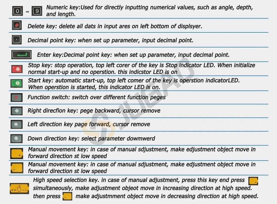
Functions of panel keys are described in Table.
Single Interface
E21 controller adopts a 160*160 dot matrix LCD displayer. The display area is shown below.
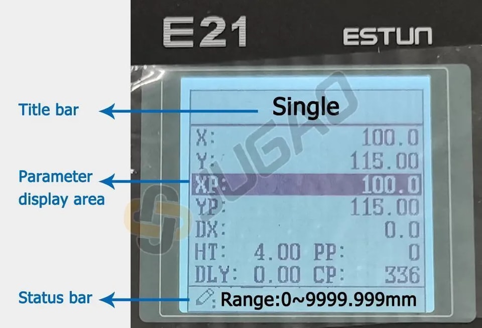
Title bar: display relevant information on the current page, such as its name, etc.
Parameter display area: display parameter name, parameter value, and system information.
Status bar: display area of input information and prompt message, etc.
The paraphrases of shortening on this page are as shown in Table.
X: The current backgsuge position
Y: The current slider position
XP: The desired backgauge position
YP: The desired slider position
DX: Backgauge retract distsnoe
HT: Holding delsy
DLY: Retracting delsy
PP: Preset workpiece
CP: Current workpiece
Single-step programming
The E21 has two programming methods, which are single-step programming and multi-step programming. Users can set up programming according to actual demand.
Single-step programming is generally used for processing a single step to finish workpiece processing. When the controller is power on, it will automatically enter a single-step program page.
Operation steps
Step 1 After starting up, the device will enter setting up the page of the single-step program automatically.
Step 2 Press  select parameter which needs to be set up, press
  numerical key to input program value, press to complete input.
Step 3 Press  , the system will execute according to this program.
Multi-step programming
Multi-step program is used for processing single workpiece of different processing steps, realize the consecutive implementation of multi-steps, and improve processing efficiency.
Operation steps
Step 1 Power on, the device displays the single-step parameter page automatically.
Step 2 Press  switch to the program manage page, switch to the program manage page .
Step 3 Press  select program serial number, or input program number directly, such as input “1”.
Step 4 Press  enter multi-step program setting page.
Step 5 Press ![]() select multi-step programming parameter which requires set up, input setting up value, press
select multi-step programming parameter which requires set up, input setting up value, press ![]() and the set up takes effect.
and the set up takes effect.
Step 6 In completion of set up, press  enter step parameter set page.
Step 7 Press  , select step parameter that needs to be set up, input program value,press
 ![]() , and the setup takes effect.
, and the setup takes effect.
Step 8 Press ![]() to switch over between steps. If the current step is the first step, press
to switch over between steps. If the current step is the first step, press ![]() to enter the last page of the step parameter setting; if the current step is the last one, press
to enter the last page of the step parameter setting; if the current step is the last one, press ![]() to enter the first page of the step parameter setting.
to enter the first page of the step parameter setting.
Step 9 Press  , system will operate according to this program.
Parameter setting
Users can setup all parameters required for normal operation of the system, including system parameter, X axis parameter and Y axis parameter.
Step 1 On program management page, press  to enter programming constant page, On this page, programming constant can be set.
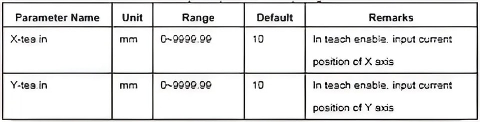
Step 2 Range of programming constant setup is shown in Table
Step 3 Input password “1212”, press  to enter the Teach Page .
Step 4 Step up parameter, parameter setup range is shown in Table.
Step 5 Press  , return to programming constant page,
Alarm
The device can detect internal or external abnormity automatically and send out alarm prompt. Alarm message is available on alarm list.
Step 1 On programming management page, press  to enter programming constant page.
Step 2 On programming constant page, press ![]() to enter “Alarm history” page to view all alarm history. the latest 6 alarms, alarm number and causes can be viewed on this page.
to enter “Alarm history” page to view all alarm history. the latest 6 alarms, alarm number and causes can be viewed on this page.
Common fault and troubleshooting
1. Controller Will Not Power On / No Display
Fault Symptoms:
The screen is blank.
No indicator lights are on.
Possible Causes & Troubleshooting:
C1: Main Power Supply Issue.
Check: Ensure the main disconnect switch for the machine is turned ON.
Check: Verify the main power cable is connected and the voltage is correct.
C2: Machine Door/Safety Guard Open.
Check: Ensure all electrical cabinet doors and safety guards are properly closed. Many machines have safety interlocks that prevent power-up.
C3: Fuse Blown.
Check: Inspect the main fuses in the machine's electrical cabinet.
C4: Faulty Power Supply Unit.
Check: The internal DC power supply (e.g., 24V DC) for the controller might have failed. This requires a qualified electrician.
2. Axes (Y1, Y2, X, R) Do Not Move or Show "Following Error" / "Axis Fault"
Fault Symptoms:
Axis does not respond to manual commands.
Controller displays an error message about axis drive or following error.
One side (Y1 or Y2) is lower/higher than the other (out of sync).
Possible Causes & Troubleshooting:
C1: Servo Drive / Amplifier Fault.
Check: Look for an error code on the servo drive unit itself (usually located in the electrical cabinet). Refer to the drive manufacturer's manual.
Action: Reset the fault by powering the machine off and on. If it persists, note the error code for technical support.
C2: Encoder / Feedback Cable Problem.
Check: Inspect the encoder cables connected to the back of the servo motors for damage or loose connections.
C3: Mechanical Obstruction.
Check: Manually check if the ram (Y-axis) or backgauge (X-axis) can move freely. There might be a physical jam.
C4: Motor Brake Engaged.
Check: The servo motor brake (especially on Y-axis) may not be releasing. You might hear a humming sound from the motor but no movement.
3. "Axis Not Referenced" or "Please Set Reference" Error
Fault Symptoms:
The machine cannot start a cycle.
The controller requests a reference procedure.
Possible Causes & Troubleshooting:
C1: Machine was Powered Down.
Action: This is a standard procedure. You must perform the "Reference" or "Zero Return" operation after the machine is powered on. Navigate to the manual screen and execute the reference cycle for all axes.
C2: Reference Switch / Proximity Sensor Fault.
Check: The sensor that detects the home position might be dirty, misaligned, or faulty. This often requires a technician.
4. "Overload" or "High Pressure" Alarm
Fault Symptoms:
Alarm occurs during the bending cycle, often near the bottom.
Possible Causes & Troubleshooting:
C1: Incorrect Tonnage (Pressure) Setting.
Check: The programmed bending pressure is too high for the material or the machine's capacity. Review and reduce the pressure setting in the program.
C2: Incorrect Die Selection.
Check: Using a V-die that is too small for the material thickness requires excessive force. Verify the V-die opening is correct for the material (typically, V-opening = 8 x Material Thickness).
C3: Bending Outside the Machine Capacity.
Check: You might be trying to bend a material that is too thick or too long for the machine's rated capacity.
5. Inconsistent Bending Angle
Fault Symptoms:
The bend angle varies from part to part, even with the same program.
Possible Causes & Troubleshooting:
C1: Material Variations.
Check: Inconsistent material thickness, hardness, or grain direction can cause angle variation. Check material certificates.
C2: Worn or Incorrect Tooling.
Check: Inspect the punch and die for wear or damage. Ensure the correct tools are used for the specified angle.
C3: Lack of Crowning Compensation.
Action: If bending long sheets, the machine's bed may deflect. Use the "Crowning" function (manual or automatic) to compensate for this deflection. Re-calibrate if necessary.
C4: Unstable Hydraulic System.
Check: Low hydraulic oil level, dirty oil, or a faulty valve can cause pressure instability. Check the oil level and temperature.
6. Backgauge (X, R, Z) Does Not Reach Position or is Inaccurate
Fault Symptoms:
The backgauge stops at the wrong position or vibrates when stopping.
Possible Causes & Troubleshooting:
C1: Mechanical Obstruction or Misalignment.
Check: Look for chips, debris, or burrs on the backgauge rails and screws. Clean and lubricate the guideways.
C2: Loose Coupling or Drive Belt.
Check: The coupling between the servo motor and the ball screw, or the drive belt (if applicable), might be loose.
C3: Backlash.
Action: Over time, mechanical wear can cause backlash. The controller often has a "Backlash Compensation" setting that can be adjusted by a technician.
General Troubleshooting Flowchart
1. Note the Exact Error Message on the E21 display.
2. Consult the Machine Manufacturer's Manual. It has the most specific error codes and procedures.
3. Perform a Simple Reset: Power the machine down completely, wait for 10 seconds, and power it back on.
4. Check for Obvious Issues: Loose wires, tripped circuit breakers, low hydraulic oil, unusual noises.
5. Isolate the Problem: Determine if it's a control issue (controller, programming), electrical (motor, drive, sensor), or mechanical (jammed axis, worn tooling).
6. Contact Technical Support: If the problem is not resolved with basic checks, provide them with the exact error message and the steps you have already taken.
Remember: Only qualified personnel should perform internal electrical repairs.
Contact Us