
How can precision be improved through the setup and calibration of pipe bending machines?
2026-10-14

When it comes down to it, bending precision hinges on two things: correct setup and accurate calibration. If the setup is wrong, subsequent adjustments are futile; if the calibration is off, even the best machine cannot produce parts that meet specifications. I have seen many workshops with high-quality equipment where the bending angles fluctuated inconsistently; upon investigation, the root cause invariably lay in the setup and calibration processes.
I. Pre-setup Preparations
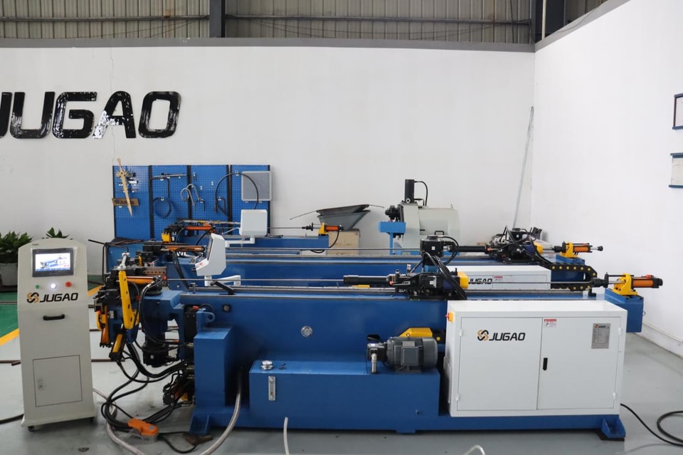
Clear and tidy the workspace first. Clutter around the machine increases the risk of accidental bumps during operation and hinders the monitoring of the machine's running status. Ensure the machine itself is securely anchored and that the anchor bolts are not loose. Verify the base's levelness using a precision level; even the slightest unevenness can result in inaccurate bending angles.
II. Proper Tooling Selection is Fundamental
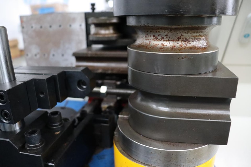
Components such as the bending die, clamping die, pressure die, mandrel, and wiper die must be selected based on the tubing's material, wall thickness, and outer diameter. Stainless steel and carbon steel require different tooling, as do thin-walled and thick-walled tubes. Incorrect tooling selection is difficult to rectify later, regardless of parameter adjustments.
Install the selected tooling carefully. Ensure the mandrel is centered, the pressure die is flush with the bending die, and the clamping system is securely fastened. Clean the mounting surfaces thoroughly to ensure no metal chips or sludge are trapped underneath. Finally, apply lubricant after installation to reduce friction during the bending process.
III. Machine Parameter Configuration
Access the control system and input parameters such as bending angle, bending speed, clamping pressure, and mandrel retraction distance. These values are not fixed; they must be adjusted based on the specific tubing material and bending radius. Use slower bending speeds for high-strength steel to prevent cracking, and exercise finer control over aluminum tubing to avoid surface deformation. When processing a specific size for the first time, start with conservative parameters and gradually optimize them after performing test bends.
IV. Calibration Steps
Step 1: Zeroing all axes. Return the rotation axis, bending arm, and feeding carriage to their zero positions. Accurate zeroing establishes the reference point for all subsequent actions. This is particularly critical for parts with multiple bends, as errors will accumulate if the zero position is inaccurate.
Step 2: Calibrating the bending angle. Bend a test piece, measure the actual angle using a digital protractor, and compare it with the set value. Metals exhibit springback, so compensation is required. Add the difference between the measured angle and the preset angle to the compensation value, then test another piece until the angles match.
Step 3: Calibrating the feed length. For machines with automatic feeding, ensure the feed axis travels to the correct position. A deviation of just 0.5 mm can cause misalignment at the ends after multiple bends. Perform several feed tests, measure the actual displacement, and fine-tune the servo parameters.
Step 4: Calibrating the rotation axis. Complex parts require rotation by a specific angle between bends. Use a protractor or rotary gauge to check the actual rotation angle against the set value; if a deviation exists, adjust the rotation calibration value on the control panel.
Step 5: Full test bend. Once all axes are calibrated, run the complete program and inspect the part against the engineering drawings, checking for ovality, wall thinning, bending radius, and angular accuracy. The machine may only proceed to mass production once all specifications are met.
V. What issues can setup and calibration resolve?
Springback control becomes more precise, and angular consistency improves. Proper die alignment reduces the risk of tube wrinkling and cracking. Accurate calibration of the feeding and rotation axes enhances the dimensional accuracy of multi-bend parts. With less need for rework and fewer adjustments, production efficiency naturally increases.
VI. Practical tips
Check the calibration after changing major tooling or every 200–300 bending cycles. Parts requiring high precision demand more frequent checks.
Perform a test bend when switching material batches. Tubing from different suppliers or batches may exhibit varying springback characteristics, so existing compensation values might not be suitable.
Stainless steel exhibits significant springback; ensure adequate mandrel support, reduce the bending speed, and appropriately increase the compensation angle.
Once all parameters are optimized, save and archive them. You can recall these settings directly for future production of the same specifications, saving time otherwise spent on repeated trial and error.
VII. Frequently Asked Questions
How often should the pipe bender be calibrated? Calibration is necessary after changing molds, before high-volume production runs, or whenever you notice the bending angle starting to drift. There is no fixed schedule; it depends on the intensity of usage.
How can stainless steel pipe springback be controlled? You need to address three key areas simultaneously: using appropriate mandrel support, reducing the bending speed, and accurately compensating for the springback value.
Is a test bend required every time the pipe material changes? Yes. Material properties vary across different types and batches, so a test bend is the most reliable way to verify the setup.
While setup and calibration may seem like tedious tasks, they are the foundation of bending precision. Investing the time to get this step right ensures a smooth production process later on.
Contact Us