-
tel:
+86-13222111178 -
email:
info@ntjugao.com


Why Is the DELEM DA-69S Automatic Mode User-Friendly?
Why Is the DELEM DA-69S Automatic Mode User-Friendly?
Oct 23, 2025
In the field of advanced press brake operations, the DELEM DA-69S Automatic Mode stands out for its user-friendly design. Whether you are an experienced technician or a newcomer to press brakes, this article will take you through the core advantages of this mode and explain how it simplifies metalworking processes and improves operational efficiency.
I. Intuitive Interface Design of the DELEM DA-69S Automatic Mode
Interface design is key to enhancing usability. The DA-69S Automatic Mode simplifies operational logic and optimizes information presentation, making complex bending operations more accessible.
1. Simplified Navigation Menu
The navigation menu of the DA-69S Automatic Mode is streamlined with clear operational logic:
• Tap the "Auto" button to switch the control system to automatic production mode.
• Press the "Start" key, and the program will execute each bending step sequentially without manual intervention, significantly improving efficiency.
• When switching between different products in the product library, the Automatic Mode can directly transition to the production state without repeated settings.
• When selecting a new bending program, the system will pop up a "check tools" warning to ensure the tool model and position are accurate, avoiding operational errors.

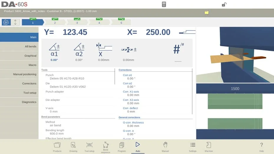
In addition, the top of the screen in Automatic Mode clearly displays the currently selected product and its description for quick confirmation. The bend selector at the top shows all pending bending steps; tapping a step selects the target operation, and pressing the start key initiates production from that step, offering greater flexibility. Large icons (tile-style buttons) above the menu facilitate quick modification of frequently used parameters, reducing operational steps.
2. Detailed Parameter Settings
This mode supports refined parameter adjustments, allowing customization based on different bending requirements to ensure processing accuracy:
• Angle Corrections (Y1/Y2 Axes): Adjustments can be made separately for the left and right sides of the machine. For example, if a programmed angle of 90° results in a 92° bend, simply set a correction value of -2°. This value is automatically saved to ensure consistency in subsequent operations.
• Y1/Y2 Axis Corrections: Applicable to absolute programming or bottoming processes. Correction parameters are stored in the currently active program, eliminating the need for repeated input.
• Auxiliary Axis Corrections: Activated based on the bend allowance of the X-axis, these corrections optimize bending accuracy and simplify workflows.
• General Corrections: Universal parameters such as thickness, angle, and X-axis adjustments are applied to all bending steps in the program, adapting to variations in materials and machine errors to ensure uniform output quality.
• Specialized Corrections: Supports deflection correction and part support axis (PST) correction, meeting the precision requirements of complex bending tasks.
• Stock and Repetition Parameters: Operators can efficiently manage the stock counter and set repeated processing steps to optimize production rhythm.
• Step Mode Option: Unlike continuous Automatic Mode, Step Mode pauses after each bending cycle, allowing operators to inspect the workpiece status and make timely adjustments.
3. Intuitive View Modes for Seamless Operation
View modes feature a user-friendly layout, enabling operators to switch functions quickly without learning complex operations, thus reducing preparation time. When entering Automatic Mode for the first time, the system defaults to the Main View, and other view modes can be selected on the right side of the screen. Switching views does not change bending data or interrupt the start status. The functions of each view are as follows:
• Main View (Main): Displays both numerical data and graphical information (if available) for bending. It supports direct programming of correction parameters and switching between graphical/numerical views. The bending position can be checked via zoom, pan, and rotate functions. The tool view automatically focuses on the currently used tool, indicating the correct tool station.
• All Bends View (All Bends): Shows all bending data in a tabular format, with the option to display or hide the graphical panel. Parameters are arranged in rows for easy batch viewing.
• Graphical View (Graphical): Provides a full-screen graphical interface of the bending process, supporting switching to 3D view for detailed observation. It also allows adjusting the viewing angle, zoom ratio, and checking photo views of specific steps.
• Macro View (Macro): Displays axis values in a large-font list, suitable for scenarios where operations are performed away from the control panel. It can monitor both the target and actual positions of all axes simultaneously.
• Manual Positioning View (Manual Positioning): Shows axis values in a large size, supporting control and adjustment of axis positions using a handwheel. Pressing the "teach indicator" arrow (located between the actual value and programmed value) records the current axis value into the program step. If an optional external hand terminal is equipped, it also enables remote control of the handwheel for teaching axes and bending positions.
• Corrections View (Corrections): Lists correction values for all bending steps and supports adjustments as needed. When an α1 correction value is entered, the system will automatically copy it to α2, maintain the difference between the two, or leave α2 unaffected, depending on the "Angle correction programming" parameter. The "Stored correction" column (displayed when the angle correction database is activated) marks the correction value for each bend; a blank entry indicates no record in the database, and a ">" mark indicates identical bend values. Clicking "All From Stored" synchronizes all bending correction values in the program to match the database values. In addition, it supports adding entries to the allowance table via "Bend Allowance" and calculating correction values from measured angles (entering a single measured angle applies it uniformly, while entering left/right/middle values enables absolute crowning correction). An optional protractor can directly input measured values, and correction values are updated after a new bending cycle.
• Tool Setup View (Tool Setup): Displays the tool configuration required for the current program, allowing inspection of tool properties and positions but not modifications. To adjust tools, exit Automatic Mode and access the "Tool Setup" menu.
• Diagnostics View (Diagnostics): Primarily used for maintenance, it monitors the operating status of independent axes and the I/O status of the control system, providing data support for troubleshooting.
II. Additional Functions for Enhancing Precision and Productivity
Beyond interface design, the DA-69S Automatic Mode is equipped with a range of practical functions to further enhance processing precision and production efficiency.
1. Notes Function (Notes)
Operators can add notes to products or programs in Automatic Mode:
• Notes can be general descriptions or details for specific bending steps, and PDF reference documents can also be attached.
• A "notes indicator" on the screen signals the presence of new notes; tapping it allows viewing, ensuring key information is accessible at all times.
2. Bumping/Chaining Correction
Supports setting general correction parameters for bumping or chaining bending steps. Tapping "Bumping Corr." or "Chaining Corr." opens a separate window for entering correction values:
• When modifying the general angle correction, all associated individual correction values are automatically recalculated, and vice versa.
• α1 and α2 axes can have independent correction values. After entering a correction value for α1, the system will automatically synchronize it to α2, maintain the difference between the two, or leave α2 unaffected, based on the "Angle correction programming" parameter. To adjust α2, operate directly in its bumping/chaining correction window or modify its individual correction values.
3. Test Bend Mode
This mode is designed specifically for fine-tuning, helping operators optimize parameters before formal production:
• When activated, all axes remain in the retracted position after the first bending cycle. If part support is enabled, the support axis maintains its current angle.
• The Y-axis stops at the Upper Dead Point (UDP), allowing operators to measure the bending angle and make corrections. After corrections are completed, the part support axis resumes operation when the Y-axis passes the specified position, ensuring precision in subsequent bending.
4. Shop Floor Control & Job List Function
Simplifies production management processes and supports multi-batch monitoring and progress tracking:
• When the system is in job production, a "Job indicator" shows the current status; tapping it allows viewing and managing jobs.
• When needing to switch product batches in the job list, press the "Activate Product" function key, and the system will directly switch to the target product.
• During production, operators can update the "number of trashed products"; the system automatically adjusts the "produced count", which can also be modified manually. Both operators and job managers can add production records or notes in the "comment field".
• Job status is divided into four categories:
◦ New: No products in this batch have been produced yet;
◦ Incomplete: The target output of this batch has not been reached;
◦ In Progress: This batch has been loaded into the machine and is in production;
◦ Finished: Production of this batch has been confirmed as completed.
• A job remains active until a new product or job is selected in "Products Mode". After loading a new product, the original job is automatically deactivated and must be reselected and started if needed.
III. Frequently Asked Questions (FAQ)
1. How does the Shop Floor Control function support the DELEM DA-69S Automatic Mode?
The Shop Floor Control function allows operators to monitor multiple production batches simultaneously, update product counts in real time, and track production progress accurately. This reduces manual statistical work and further improves the operational efficiency and data accuracy of the Automatic Mode.
2. How to calibrate the press brake accurately when using the DA-69S Automatic Mode?
First, ensure the press brake is level. Then, use a digital gauge to measure the angle of the bending die and adjust parameters according to the calibration guidelines provided by the manufacturer. After adjustment, verify the calibration result to ensure it meets processing precision requirements.
3. What is the maintenance frequency for the press brake when the DA-69S Automatic Mode is enabled?
Routine maintenance is recommended every 500 hours of operation. This includes inspecting the wear of key components (such as axes and dies), cleaning debris from the machine, and lubricating moving parts to maintain optimal operating conditions in the Automatic Mode.
IV. Conclusion
The high usability of the DELEM DA-69S Automatic Mode stems from its dual advantages of "intuitive interface design + enhanced precision functions". The interface simplifies operational logic and reduces the learning curve, while the additional functions ensure precision and efficiency. Both new and experienced operators can master it quickly, streamlining the bending process in the workshop.
If you need further details on the specific operation of the DA-69S Automatic Mode or have customized inquiries, please feel free to contact our team for support. You can also refer to more related resources to optimize your metalworking operation plan.
Would you like me to compile a Core Operation Quick Reference Table for DELEM DA-69S Automatic Mode? It will refine key steps of the navigation menu, parameter settings, and view modes into a concise table, making it convenient for you to quickly reference and use during on-site operations.


Recent Posts

October 26, 2016
The Most Successful Engineering Contractor
Apr 16, 2026
Replacement Frequency of Welding Robot Contact Tips

Apr 16, 2026
Rotational Degrees of Freedom in Welding Robots


Contact US
Product Information
Quantity
Unit
Piece
Support order samples, customization, wholesale direct, and complete payment. If the product you look for does not have corresponding customized content, pls fill out the form below to contact us, and we will reply ASAP.