-
tel:
+86-13222111178 -
email:
info@ntjugao.com


ESA S530 Bending Sequence Calculation: Principles, Operation and Application Guide
ESA S530 Bending Sequence Calculation: Principles, Operation and Application Guide
Oct 31, 2025
Table of Contents
• Introduction
• Automatic Bending Sequence Calculation (Optional Feature)
◦ Calculation Interface
◦ Optimization Results
◦ Simulation Function
◦ Bearing/Support Setup
• Manual Bending Sequence Calculation (Optional Feature)
◦ Results of the Optimization Process
◦ Simulation Operation
◦ Bearing/Support Configuration
◦ Modification of Bending Sequence
• Steps for Box Bending Operation
• Frequently Asked Questions (FAQ)
◦ How does the ESA S530 enhance the bending process?
◦ Can I manually modify the bending sequence in the ESA S530?
◦ What should I do if an error occurs during the ESA S530 Bending Sequence Calculation?
• Conclusion
Introduction
In the field of metal fabrication, precise bending is a core link in ensuring workpiece quality, and the bending sequence calculation function of the ESA S530 is exactly the key technology to achieve this goal. As a core feature of the ESA S530 system, it intelligently optimizes the bending order of metal sheets, reducing operational errors and material waste while ensuring that workpieces fully meet design specifications. Whether it is to improve production efficiency or maintain stable processing quality, this function plays an irreplaceable role. This article will fully analyze the working logic, core advantages and practical operation methods of the ESA S530 Bending Sequence Calculation, providing practical guidance for beginners to get started and senior operators to optimize processes, helping to improve the overall level of metalworking operations.
Automatic Bending Sequence Calculation (Optional Feature)
The trigger path for automatic bending sequence calculation is simple: start the process from the workpiece drawing interface and press the [Calculate] key to enter the operation interface. This mode realizes the independent optimization of the bending sequence through numerical control technology, while retaining the coordination space with the manual mode to adapt to the needs of different production scenarios.
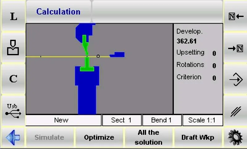
Calculation Interface
The calculation interface is the "planning center" before bending. It not only displays the pre-bending simulation state of the workpiece in real time, but also clearly shows the positional relationship of the core components of the bending machine - punch, die and stop, helping operators grasp the relative position between the equipment and the workpiece in advance. There are three sub-windows on the right side of the interface, which dynamically display the rotation angle and flipping times of the workpiece respectively. At the same time, it is equipped with a "full solution retrieval" function, which can traverse all potential bending paths and provide complete data support for subsequent optimization.
In addition, the system ensures processing safety and efficiency through numerical control logic: it always keeps the larger area of the metal sheet within the controllable range of the operator to reduce operational risks. Operators can also adjust the calculation standards according to production needs and flexibly switch between automatic/manual modes to further improve process adaptability.
Coordination Logic between Automatic and Manual Modes
The bending sequence calculation of the ESA S530 does not run in a single mode, but realizes flexible processing through the coordination of "automatic + manual" dual modes:
• Automatic Mode: Relying on numerical control algorithms, the system independently completes the calculation of the optimal bending sequence without manual intervention. After pressing the [Optimize] key, the system will automatically screen out the scheme with the highest efficiency and the smallest error based on workpiece parameters (such as material, thickness, bending angle).
• Manual Mode: Operators can independently define part or all of the bending steps and make fine adjustments through exclusive function keys: the [Bend] key is used to lock the selected bending action, and the [Turn] key can control the rotation angle of the workpiece; after completing the custom settings, press the [Optimize] key, and the system will integrate the manually specified parameters into the automatic calculation to generate a scheme that takes into account both "operational intention" and "process optimization".
Optimization Results
The feedback logic of optimization results is clear, facilitating operators to make quick judgments and decisions:
• When the Scheme is Not Feasible: The system pops up a "NO SOLUTION" prompt, reminding the operator to check for problems (such as conflicting bending angles, component interference, etc.) or try to adjust the bending order. If there is a collision risk for the workpiece, it will be intuitively marked in the collision area through color changes (such as red highlighting).
• Allowing Special Operations: If the collision is only "non-destructive interference" (such as temporary contact that does not affect the workpiece or equipment), the operator can choose to ignore the prompt and continue to execute the bending process.
• When the Scheme is Feasible: The system displays "Solution FOUND" and provides four core operation options:
a. [Stop]: Pause the optimization process to facilitate parameter fine-tuning of the current scheme (such as adjusting the bending angle, modifying the support position).
b. [Continue]: Continuously retrieve other potential schemes until there are no more feasible paths. If all possibilities have been checked and there is no suitable scheme, "NO SOLUTION" will be displayed finally.
c. [Simulate]: Start the bending sequence simulation. Operators can advance the process through the [Continue] key or interrupt the simulation through the [Stop] key to observe the bending process in real time.
d. [Accept]: Save the currently calculated bending parameters (such as angle, speed, support position) to the program for direct use in actual processing.
Simulation Function
The simulation function is a "preview link" to ensure bending accuracy, and the operation steps are intuitive and controllable:
1. Press the [Simulate] key, and the interface displays the state of the flat workpiece to be bent, clarifying the initial position of the first bending.
2. Select the appropriate support structure through the [Bearing/Support] key. It is necessary to ensure that there is no collision risk at the support position and that it conforms to the equipment axis movement range limits (such as X-axis and R-axis strokes).
3. Press the [Continue] key, the system executes the first bending action and displays the shape of the workpiece after bending; subsequent bending requires repeating this step to gradually advance the process.
4. If you need to pause to observe details, you can press the [Stop] key; if you need to backtrack and adjust (such as correcting the support position of the previous step), you can return to the previous step through the [Previous] key.
5. Press the [Continue] key repeatedly until the simulation of all bending steps is completed. At this time, the [Simulate] key will be displayed again, indicating the end of the simulation process.
Bearing/Support Setup
Bearing/support setup is the key to avoiding workpiece deformation and ensuring bending stability. The operation must follow the following process:
1. Press the [Simulate] key, and the interface displays the flat workpiece to be bent for the first time, clarifying the initial processing state.
2. Press the [Bearing/Support] key to switch the support type - you can select "First Support", "Second Support" or "Workpiece Support". The system will automatically judge the feasibility of the locator movement: the locator will only move to the target support position when there is no collision risk and meets the equipment limit conditions.
3. Press the [Continue] key to view the state of the workpiece after the first bending and confirm whether the support effect meets expectations.
4. Continue to press the [Continue] key to enter the second bending setup, and select the support type as needed (the locator movement still needs to meet the dual conditions of "no collision + compliance with limits").
5. During the process, you can press the [Stop] key to stop the simulation at any time, or press the [Previous] key to go back to the previous step to adjust the support parameters.
6. Continue the simulation until the [Simulate] key is displayed again, which means the full-process verification of the support setup is completed.
It should be noted that this function is located in the upper right corner of the numerical control program, side by side with the bending type icon. The system will automatically correct the position deviation of the X-axis and R-axis; if the current program is a "graphic type", the [Bearing/Support] key cannot be used in the numerical control mode, and the support adjustment must be performed by switching to the simulation interface.
Manual Bending Sequence Calculation (Optional Feature)
Manual bending sequence calculation is suitable for scenarios that require personalized adjustments. The startup path is the same as that of the automatic mode: press the [Calculate] key from the workpiece drawing interface to enter. The interface will simulate the entire bending process in detail, including the visual presentation of the upper and lower bodies of the bending machine, punch, die, locator and workpiece before bending; the three panels on the right will dynamically display the number of rotations and flipping angles of the workpiece during the calculation process (for specific diagrams, please refer to the interface description in the "Automatic Bending Sequence Calculation" chapter).
Manual Search for Bending Sequence
The core of the manual search mode is "manually leading the bending path", and the operation steps are as follows:
1. Use the arrow keys 
 to browse all bending steps and locate the target level that needs adjustment.
2. Press the [Bend] key at the target bending level to force lock the bending action; if you need to cancel it, press the [Bend] key again.
3. Press the [Turn] key to adjust the rotation angle of the workpiece to ensure that the subsequent bending matches the position of the current step.
4. After completing the forced setting of all necessary bends, press the [Optimize] key. The system will calculate the final scheme based on the manually specified sequence and combined with process constraints (such as no collision, axis stroke limit).
Results of the Optimization Process
The feedback of optimization results in manual mode is consistent with that in automatic mode, but it focuses more on "adaptability of manual adjustment":
• If the workpiece configuration (such as the manually specified bending sequence) cannot be processed, the system pops up a "Forced Solution" prompt. The operator needs to reposition the problem steps (such as conflicting bending angles, improper support positions) through the manual search function.
• Potential collision risks of machine components will be marked by color changes (such as orange warning) to assist operators in adjusting the sequence or modifying the support.
• If the collision has no damage risk (such as temporary contact between the workpiece edge and the die), the bending can be enforced; if a feasible scheme is detected, the system displays "Solution Found", and the operator can choose [Stop] to pause the optimization for adjustment, or [Accept] to integrate the calculated values into the program.
Simulation Operation
The simulation process of the manual mode is consistent with that of the automatic mode. The core difference is that "the simulation is based on the manually specified sequence":
1. Press the [Simulate] key to view the state of the flat workpiece to be bent (the initial state matches the first bending set manually).
2. Press the [Bearing/Support] key to select the support type, ensuring no collision and compliance with the axis movement limit.
3. Press the [Continue] key to execute the first bending, and repeat this step for subsequent bending; you can press [Stop] to pause or [Previous] to backtrack to verify the rationality of the manually specified sequence.
4. Continue the simulation until the [Simulate] key is displayed again. After confirming that there is no problem in the entire bending process, it can be used for actual processing.
Bearing/Support Configuration
The bearing/support configuration in manual mode has the same operation steps as that in automatic mode, but it should be noted that "the support must be adapted to the manually specified bending sequence":
• The movement of the locator must meet the dual conditions of "manually set bending position" and "no collision" to avoid support failure caused by sequence adjustment.
• If it is necessary to modify the support type, it must be operated in the simulation interface (the [Bearing/Support] function is not supported for graphic programs in the numerical control mode) to ensure the matching between the support and the bending steps.
Modification of Bending Sequence
Even after the bending sequence has been optimized, the ESA S530 still supports flexible adjustments to meet the needs of temporary process changes:
1. Use the arrow keys to browse all bending steps and locate the target bend that needs modification.
2. Press the [Bend] key to cancel the bending action, and reselect the new bending sequence (or adjust the rotation angle).
3. After completing the modification, the simulation can be started again to verify the feasibility of the new sequence, ensuring that the adjusted process is accurate and efficient.
Steps for Box Bending Operation
Box bending is a typical scenario in metal processing. The bending sequence calculation of the ESA S530 in this process must follow the "program-separated execution" logic - since the numerical control process cannot directly unfold the bent box into a flat plate, the operator needs to create two independent bending programs:
• Program 1: Used for horizontal bending, defining the lateral bending angle and position of the box side.
• Program 2: Used for vertical bending, defining the longitudinal bending parameters of the box top/bottom.
By executing these two programs in sequence, the precise forming of the box can be achieved. In addition, during the execution of multi-section programs, the ESA S530 will automatically give priority to processing the section with the narrower metal plate width, reducing the risk of sheet deformation and improving bending efficiency.
Adding a Section
To add a new processing section for box bending, follow these steps:
1. Press the designated function key (refer to the equipment operation panel accessory for the icon) to open the section management menu.
2. Select the "Change Section" option in the menu. The system will automatically create a new section, and the operator can set the bending parameters (such as angle, support position) of this section.
Canceling a Section
To delete an unnecessary section, the operation process is as follows:
1. Use the arrow keys to navigate to the target section and confirm the section number and parameters.
2. Open the section management menu and select the "Cancel Section" option.
3. The system will remove the section, and the program will automatically backtrack to the "Bend 1 of Section 1" step to ensure the continuity of the subsequent process.
Frequently Asked Questions (FAQ)
How does the ESA S530 enhance the bending process?
The ESA S530 reconstructs the bending process through "automatic bending sequence calculation": it eliminates the need for manual repeated trial and error (such as adjusting the bending sequence multiple times in traditional processes), greatly shortens the equipment debugging time; at the same time, the system optimizes the path based on numerical control algorithms, reduces operational errors, improves the overall efficiency and accuracy of metal forming operations, and lowers the material waste rate.
Can I manually modify the bending sequence in the ESA S530?
Yes. The ESA S530 supports manual adjustment of the bending sequence. According to specific production needs (such as shape constraints of special workpieces, temporary process limitations of equipment), operators can customize part or all of the bending steps through the [Bend] key and [Turn] key, taking into account both "process flexibility" and "processing accuracy".
What should I do if an error occurs during the ESA S530 Bending Sequence Calculation?
If a calculation error occurs, it is recommended to troubleshoot according to the following steps:
1. First, check the input parameters: confirm whether the basic settings such as material type, sheet thickness, and bending angle are accurate (parameter errors are common causes of failures).
2. If the parameters are correct, refer to the ESA S530 official operation manual and find the solution for the corresponding error code in the "Troubleshooting" chapter.
3. If the problem is still not resolved, contact the technical support team directly, provide the error prompt screenshot and workpiece parameters, and obtain targeted assistance.
Conclusion
Mastering the principles and operations of the ESA S530 Bending Sequence Calculation is the core prerequisite for achieving high precision and high efficiency in metal bending operations. The core logic of this process lies in: ensuring the forming quality of complex workpieces such as boxes through the strategy of "processing horizontal/vertical bending in separate programs" and "executing the section with the narrower sheet width first"; at the same time, the coordination of automatic and manual dual modes enables the system to adapt to both standardized mass production and meet personalized processing needs.
To give full play to the performance of the bending machine and ensure the smooth progress of the production process, it is recommended that operators strictly follow the above operating specifications and flexibly adjust parameters according to the workpiece characteristics in practical applications. For further help (such as obtaining more technical documents, answering specific process questions), you can contact our team at any time, or visit the official website to view the complete support materials related to bending operations, helping to continuously optimize the metal processing process.


Recent Posts

October 26, 2016
The Most Successful Engineering Contractor


May 26, 2026
Welding Defects in Laser Welding Machines
May 26, 2026
How to Get the Best Deal on a Shearing Machine
May 26, 2026
How to Improve Shearing Machine Productivity
Contact US
Product Information
Quantity
Unit
Piece
Support order samples, customization, wholesale direct, and complete payment. If the product you look for does not have corresponding customized content, pls fill out the form below to contact us, and we will reply ASAP.