-
tel:
+86-13222111178 -
email:
info@ntjugao.com


Why calibrate the K factor in sheet metal bend calculations?
Why calibrate the K factor in sheet metal bend calculations?
Oct 31, 2025
The K factor is an independent value that describes how a sheet metal bend bends/unfolds under a wide range of geometric parameters. It is also an independent value used to calculate bend compensation (BA) under a wide range of conditions, such as material thickness, bend radius/bend angle, etc. Figures 4 and 5 provide a deeper understanding of the detailed definition of the K factor.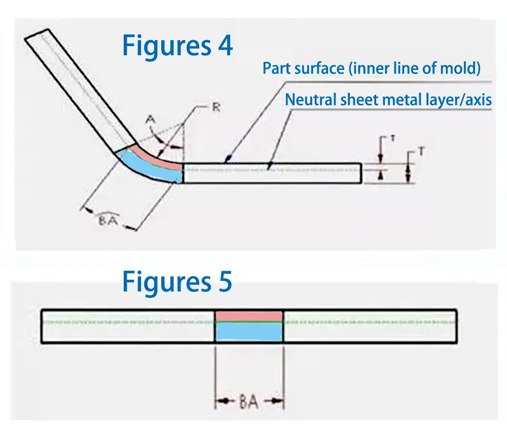
Within the material thickness of a sheet metal part, there exists a neutral layer or axis. This neutral layer, located in the bending zone, neither stretches nor compresses. This is the only area of the sheet metal that does not deform during the bend. This is represented in Figures 4 and 5 as the boundary between the pink and blue areas. During the bending process, the pink area compresses, while the blue area stretches. If the neutral layer does not deform, the length of the arc in the neutral layer in the bending zone is the same in both the bent and flattened states. Therefore, BA (bend compensation) should be equal to the length of the arc in the neutral layer in the bending zone of the sheet metal part. This arc is represented in green in Figure 4. The location of the neutral layer depends on specific material properties, such as ductility. Assume that the neutral layer is located at a distance "t" from the surface, meaning that the depth t is measured from the surface of the sheet metal part into the thickness of the sheet metal. Therefore, the radius of the neutral layer arc can be expressed as (R + t). Using this expression and the bend angle, the length of the neutral layer arc (BA) can be expressed as:
BA = Pi**(R+T)A/180
In order to simplify the definition of the neutral layer of sheet metal and consider it applicable to all material thicknesses, the concept of K factor is introduced. The specific definition is: K factor is the ratio of the thickness of the neutral layer of sheet metal to the overall thickness of the sheet metal part material, that is:
K = t/T
Therefore, the value of K will always be between 0 and 1. A K factor of 0.25 means that the neutral layer is located at 25% of the thickness of the sheet metal material of the part. Similarly, if it is 0.5, it means that the neutral layer is located at 50% of the total thickness, and so on. Combining the above two equations, we can get the following equation (8):
BA = Pi(R+K*T)A/180 (8)
Several of these values, such as A, R, and T, are determined by the actual geometry. So, back to the original question, where does the K factor come from? Again, the answer comes from the same old sources: sheet metal material suppliers, test data, experience, manuals, and so on. However, in some cases, the given value may not be the obvious K, nor may it be fully expressed in the form of equation (8). Regardless, even if the expression is not exactly the same, we can always find a connection between them.
In the process of sheet metal bending calculation, we often debug the K factor. So why do we need to debug the K factor? Because the non-90 degree bend deduction in SW can only be calculated by inputting multiple deductions, which is very troublesome. In order to avoid the technical non-90 degree bend deduction value, the K factor is used instead. So how to accurately guide the K factor for different plate thicknesses? This requires debugging. The following analysis shows how to debug:
1.The first step is to determine the actual value that needs to be deducted for different plate thicknesses. For example, the value deducted by the 6-fold knife operation for a 1.5mm thick iron plate is 2.5MM.
2.The second step is to debug K in SW. When drawing sheet metal, uniformly set the inner R to 0.1 for debugging. Because the K value is different for different inner R, you should pay attention to this. So uniformly set the inner R to 0.1 for debugging. Then some people ask, after debugging, if the inner R is not 0.1, it will be useless? In this case, if it is not 0.1, you need to change it to 0.1 and unfold it.
3:In the third step of debugging, a 10*10 plate with a thickness of 1.5 is bent in SW with an R of 0.1 at a 90-degree angle. The bending deduction is set to 2.5, and the resulting unfolding is 17.5MM.
4:The fourth step is to change the bending deduction to K factor. First set the approximate value, for example, 0.3. The unfolded shape is definitely not 17.5. Then try the K value again until it is 17.5. In this way, the K value is adjusted to 0.23, which is just the right amount to unfold to 17.5MM.
5.And so on, you can debug different numerical statistics tables.


Recent Posts

October 26, 2016
The Most Successful Engineering Contractor


![What Is Metal Plate Rolling Machine? [ Definition & Working Principle ]](https://shopsource.singoo.cc/1187/general/eJzA4YRePeWZisQ7/图片1.webp?x-oss-process=image/resize,w_100/quality,q_100)

Contact US
Product Information
Quantity
Unit
Piece
Support order samples, customization, wholesale direct, and complete payment. If the product you look for does not have corresponding customized content, pls fill out the form below to contact us, and we will reply ASAP.