-
tel:
+86-13222111178 -
email:
info@ntjugao.com


Key Configuration Steps for the DELEM DA-66T Tool
Key Configuration Steps for the DELEM DA-66T Tool
Oct 29, 2025
If you aim to become proficient in configuring the DELEM DA-66T tool, this guide is tailored for you. Grasping the configuration process is essential to boosting your machine’s performance and guaranteeing precise outcomes in bending operations. Below, we break down the core procedures and settings of tool configuration, helping you enhance operational efficiency. Let’s delve into the specifics of DELEM DA-66T configuration to ensure you fully understand each step.
1. Introduction
 To adjust or revise a tool setup for a specific product, first locate and select the product from the tool library, then launch the Tool Setup function. This initial step lays the groundwork for customizing the tool to match your production needs.
2. Standard Workflow
The standard workflow for DELEM DA-66T tool configuration starts with a comprehensive grasp of the machine’s interface layout and operational principles. A crucial preliminary step is checking for system updates—these updates often unlock enhanced functionalities that improve configuration accuracy. Mastering this basic workflow is fundamental to carrying out precise and successful tool configurations.
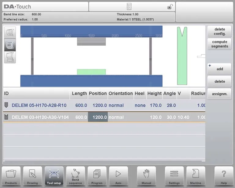
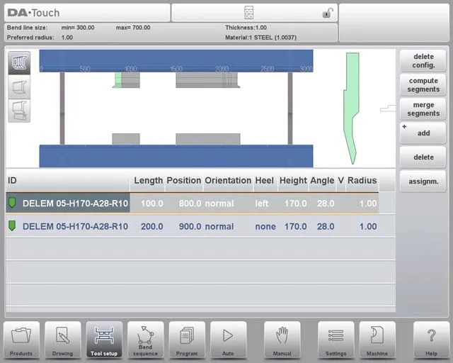
Once the Tool Setup function is activated, the upper half of the screen displays a front-facing view of the machine setup. This interface allows you to program the placement of tools within the machine. From top to bottom, the front view shows the following machine components:
• Upper machine side (press beam)
• Punch adapter (if programmed)
• Punch
• Die
• Lower machine side (table)
Note that whether a punch adapter can be programmed depends on the “enable adapters” parameter in the same Machine mode.
3. Tool Selection
Tool selection is a pivotal part of DELEM DA-66T configuration. When starting a new tool configuration, the machine’s opening is empty—here’s how to proceed with selection:
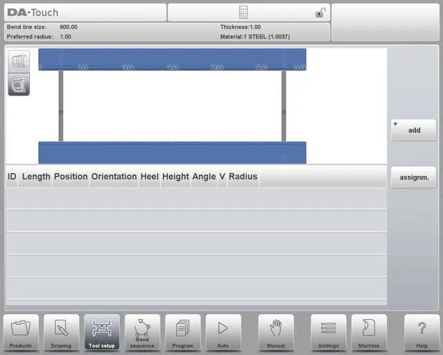
First, click “Add” to include a tool in the configuration. You can choose a punch, die, or adapter (if the adapter function is enabled). Once a tool (e.g., a punch) is selected, it is placed in the machine using the maximum available length.
After placement, you can modify the tool ID by selecting the Punch ID on the screen and tapping the List view.
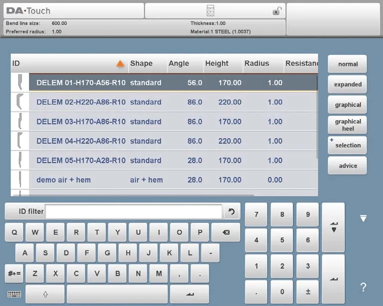
On this screen, the “Advise” feature provides a curated list of available tools, with selection based on four key criteria:
• Product Radius: The tool should generate a radius close to the target, with a tolerance of +/- 50% relative to the preferred radius.
• Bending Force: The required bending force must not exceed the tool’s load-bearing capacity.
• Tool Angle: The tool’s angle must be less than or equal to the angle required for the product.
• Bend Method: The tool must align with the intended bending method (e.g., use hemming tools for products that require hem bends).
To view all available tools, tap “Show All”. For efficient selection, start by picking Multi-V or Vario-V dies that fit your production requirements, and use the die feature preselection option to speed up the process.
3.1 Multi-V Die Feature Preselection
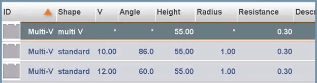
Multi-V dies come with multiple V-shaped or U-shaped openings, and their preselection involves three key steps:
• Selecting Openings: You can manually choose a specific opening for the Multi-V die, which gives you precise control over the calculation of the bending sequence.
• Using Multi-V (V = *): Alternatively, select the Multi-V die with the setting “V = *”. In this case, the control system will automatically pick the opening that brings the product radius closest to your programmed specification.
• Dynamic Adjustment: During the calculation of the bending sequence, if another opening is determined to be more suitable, the system will switch to this new opening for the remaining, uncalculated bends—optimizing the bending process for better results.
This method ensures flexibility and accuracy in DELEM DA-66T tool configuration.
3.2 Vario-V Die Selection and Setup
Vario-V dies have adjustable V-shaped or U-shaped openings, and their selection process is similar to that of other dies. Here’s a simplified breakdown:
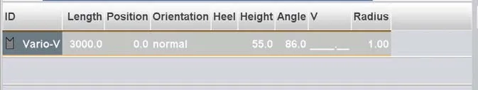
• Selection Process: Choose the Vario-V die just like any other die. Initially, the V-value (opening size) is not programmed.
• Bend Sequence Creation: You can proceed to create a bending sequence immediately—the system will automatically select the most appropriate V-value based on the available Vario-V positions.
• Programmed V-Value: If you manually program a specific V-value, the system will use this value to calculate the bending sequence.
• Discrete Positions: For Vario-V dies with fixed discrete positions, only these positions are usable. If you program a different V-value, the system will select the nearest available position.
• Adjusting V-Openings: You can modify the selected V-opening (for Multi-V dies) or V-value (for Vario-V dies). Use the “Modify, Shift Die” function and tap the value to make adjustments.
• Program Mode Adjustments: Similar adjustments can also be made using the Die Positioning function in Program mode.
Integrating these steps into your DELEM DA-66T configuration helps optimize bending operations.
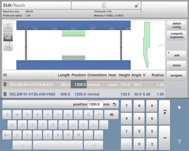
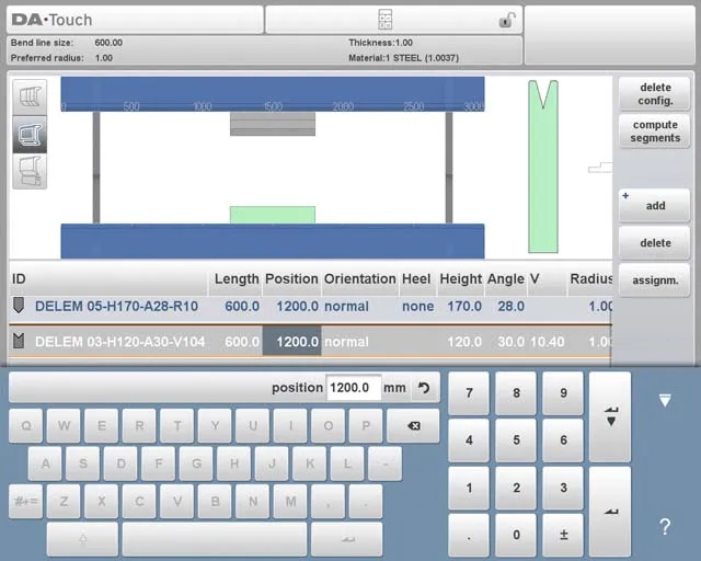
3.3 Tool Positioning and Repositioning
Adjusting the position of tools in DELEM DA-66T configuration is intuitive. Follow these steps to manage tool settings efficiently:
1. Modify Length and Placement:
◦ Move the cursor to the target field, enter the new parameter value, and press ENTER— the tool will then be updated with the new settings.
◦ You can also select a tool by tapping it, then drag it to the desired location to adjust its position.
1. Precision Repositioning:
◦ The system includes an enhanced dragging feature: during dragging, move your finger downward to slow the positioning speed, enabling more precise placement.
◦ A snapping function aids alignment: when tools are within the snapping range, a red line appears, indicating that the tool is aligned with the machine’s upper edge, lower edge, or center.
2. Tool Setup Adjustments:
◦ Once a punch is finalized, a die with a default ID (matching the punch’s length and position) is automatically placed below the punch.
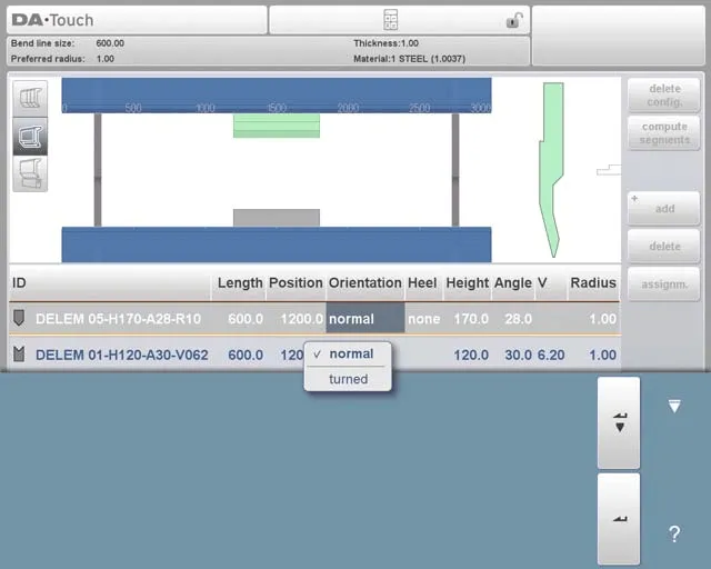
◦ Use the available functions to adjust the tool setup: add or deactivate punches/dies, move tools, change their length, adjust their orientation, or modify heel types.
3. Tool Management Functions:
◦ Delete Config.: Erase the current configuration to start a new one from scratch.
◦ Add: Introduce a new tool (punch, die, or adapter, if enabled) to the configuration.
◦ Delete: Remove the currently selected tool from the setup.
When selecting and setting tools, pay close attention to positioning and repositioning—this is critical for achieving the desired bending results and maintaining product quality.
4. Tool Segmentation
For DELEM DA-66T configuration, the control system supports creating custom tool sizes through proper segmentation. Below is an overview of the segmentation function, including the three view modes available in Tool Setup:
• Tool Setup and Segmentation Logic: The control system enables efficient tool segmentation, which is determined by the preprogrammed segments for each individual tool. You can configure these segments in Machine mode, under the Punches and Bottom Dies libraries.
• Three View Modes in Tool Setup: The Tool Setup screen offers three view modes to facilitate segmentation:
 Segmentation View: Displays detailed information about tool segments and allows you to manage individual segments.
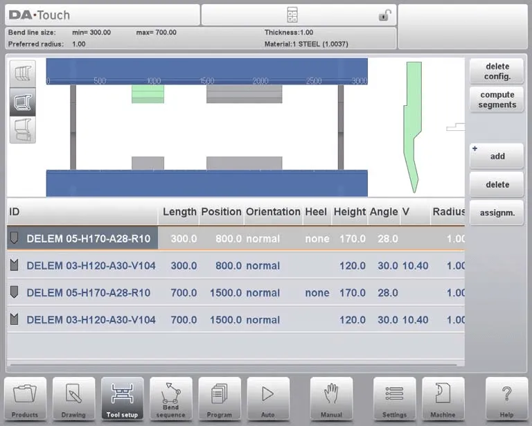
 Tool Setup View: Shows the tools required for production and lets you set up the desired tool configuration.
 Tool Station View: Enables you to view, select, and manage tool stations.
You can switch between these views using the buttons on the left side of the machine’s front panel, which enhances your ability to configure tools effectively. For detailed instructions on programming segments in the tool library, refer to the concluding section of this guide.
5. Segmentation of Individual Tools
After setting up the tools needed for your product, the Bend Sequence mode can calculate the most efficient bending sequence. Here’s a simplified breakdown of individual tool segmentation:
• Segmentation Option: If necessary, you can segment tools—this helps select the correct segments to achieve the required tool length.
• Automatic Calculation: The tool segmentation function automatically computes the required segmentation. It uses parameters such as “maximum inter-tool distance” and, optionally, “tool length tolerance” to find the optimal solution.
For precise control, focus on segmenting individual tools:
• Use the Tool View to review available tools and their configurations.
• Use assignments to categorize tools based on usage and necessity.
• In the Segmentation View, ensure each segment is properly recorded in the tool library. Maintaining an organized library simplifies tool retrieval and improves machine usability.
5.1 Tool View
In DELEM DA-66T configuration, you can start tool segmentation by clicking the segmentation function in the Tool View interface. The system calculates segmentation based on preprogrammed segment lengths and the current availability of segments, taking into account all stations using the same tool.
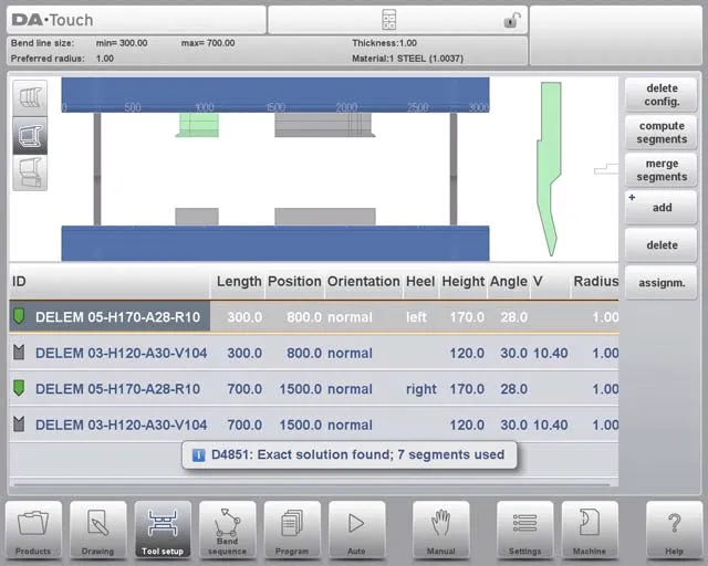
The results are displayed with status indicators to show optimization progress:
• A green indicator signifies an exact match between the required and available segments.
• A yellow indicator denotes a valid but approximate segment length (within the allowed tolerance).
• A red indicator means no valid segmentation is possible.
You can interrupt the segmentation process by clicking “Cancel” or “Stop”. Use the “Merge Segments” button to revert a segmented tool to its non-segmented state. Additionally, adjusting a tool’s properties will automatically merge its segments.
Assignments
To view the assignments used in segmentation calculations, tap the “Assignments” button. The available assignments include:
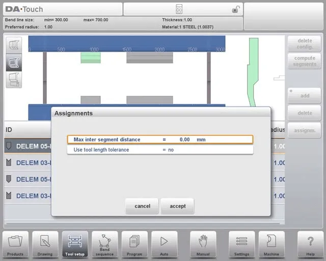
• Max Inter-Segment Distance: The maximum allowed distance between adjacent segments.
• Use Tool Length Tolerance: Enables this tolerance to accommodate minor deviations in segmentation.
5.2 Segmentation View
In the Segmentation View of DELEM DA-66T configuration, only the segments of the selected tool are displayed.
You can move and modify these segments, but note that these changes do not account for segments in stock. Also, altering the tool’s length or type will reset the segmentation, requiring you to regenerate the segments.
5.3 Segments in the Tool Library
To enable segment usage in DELEM DA-66T configuration, you need to complete the library setup in Machine mode—navigate to either the Punches or Bottom Dies section.
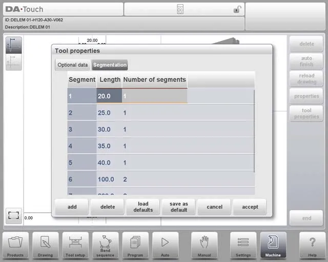
For each tool, you can program the segment length, optional heel shape, and available segments on the “Segmentation” tab.
6. Station Selection and Repositioning
In DELEM DA-66T configuration, the Station View is the third perspective for tool setup. Here’s a simplified guide to using it:
• Station Highlighting: When in Station View, entire toolstations are highlighted once you select them—this makes it easy to identify the stations you are working with.
• Repositioning Tools: You can reposition toolstations in two ways: either by programming a new position or by dragging the station to a new location on the machine interface.
• Automatic Toolstation Definition: A toolstation is automatically defined when a punch overlaps with a die. This applies even if there is a slight position shift (as long as overlap remains) or if two punches are paired with a single die—this is particularly useful for constrained bends.
• Maintaining Relative Positioning: When repositioning stations, their relative positions remain unchanged, ensuring the integrity of your setup is preserved.
• No Impact on Tool Details: Importantly, the Station View only manages the spatial arrangement of toolstations—it does not modify any tool specifications (e.g., length, angle, or load capacity).

Understanding these features of the Station View allows you to effectively manage and reposition tools, optimizing machine performance.
7. Frequently Asked Questions (FAQ)
Q1: Can I reposition toolstations without affecting their setup in DELEM DA-66T?
A1: Yes. In Station View, you can reposition toolstations while keeping their relative positions intact. This ensures your setup remains consistent and accurate.
Q2: How do I start the DELEM DA-66T tool configuration process?
A2: Begin by accessing the machine’s interface and navigating to the tool settings menu. Familiarize yourself with the available options first, and make sure to install all initial system updates—this ensures the machine operates with optimal performance.
Q3: Does changing the position of toolstations affect the tool details in DELEM DA-66T?
A3: No. Repositioning toolstations only adjusts their spatial layout; it does not alter any tool details (such as dimensions, load capacity, or angle). The Station View is exclusively for managing placement, not tool specifications.
8. Conclusion
In summary, becoming proficient in DELEM DA-66T tool configuration requires mastering key steps: accessing and navigating the Tool Setup interface, selecting tools that match your production needs, and managing tool positioning and station alignment. Proper configuration not only boosts machine performance but also ensures precision and efficiency in bending operations.
To maximize the utility of your DELEM DA-66T, make sure to check for system updates regularly and maintain a well-organized tool library. Paying consistent attention to these details will help you get the most out of your press brake’s productivity.
If you need further support or have questions about DELEM DA-66T tool configuration, feel free to contact our team. We also recommend exploring our additional resources and documentation to gain more insights into optimizing your machine’s performance.


Recent Posts

October 26, 2016
The Most Successful Engineering Contractor


May 26, 2026
Welding Defects in Laser Welding Machines
May 26, 2026
How to Get the Best Deal on a Shearing Machine
May 26, 2026
How to Improve Shearing Machine Productivity
Contact US
Product Information
Quantity
Unit
Piece
Support order samples, customization, wholesale direct, and complete payment. If the product you look for does not have corresponding customized content, pls fill out the form below to contact us, and we will reply ASAP.