- tel:+86-13222111178
- email:info@ntjugao.com
T15 Bending Machine Operation Manual
T15 Bending Machine Operation Manual

Chapter 1 Overview
1.1 Main interface
After the system power-on and boot-up is completed, it enters the main page, as shown in Figure .
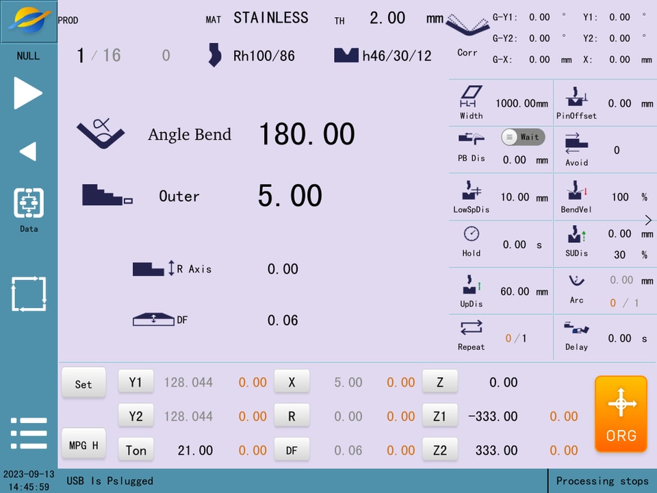
1.On the left side is the function bar, including the left and right button  , the power level login button
  , the status display button
  , the menu button
  and the system date and time display.
2.Click on the power level login and enter your username and password before you enter the high power level and can see more of the page.
3.Menubar:This system is divided into 6 menus according to the main functions, of which: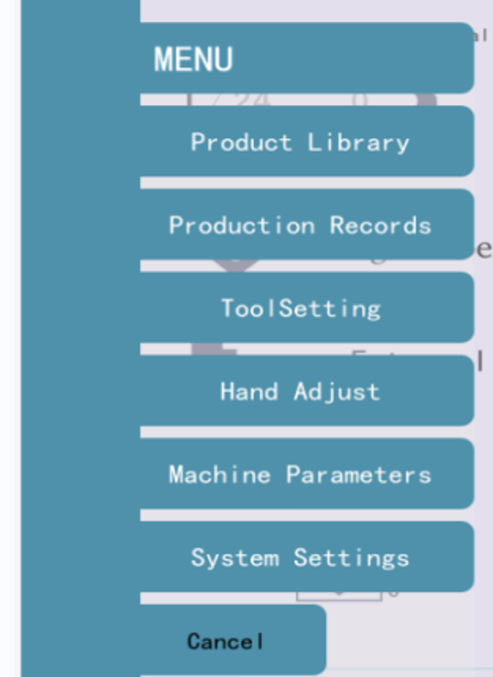
Product library: products can be created, stored, read and deleted.
Production records: setting production targets and keeping production records.
Tool setting: Enter the tool setting interface to adjust the maximum opening after changing the mold.
Manual axis adjustment: In this screen, you can perform manual actions on individual axes.
Machine parameters: machine configuration, machine status and tuning parameters.
System settings: system time, data backup and recovery, alarm records, power level settings, etc.
Chapter 2 Product Library
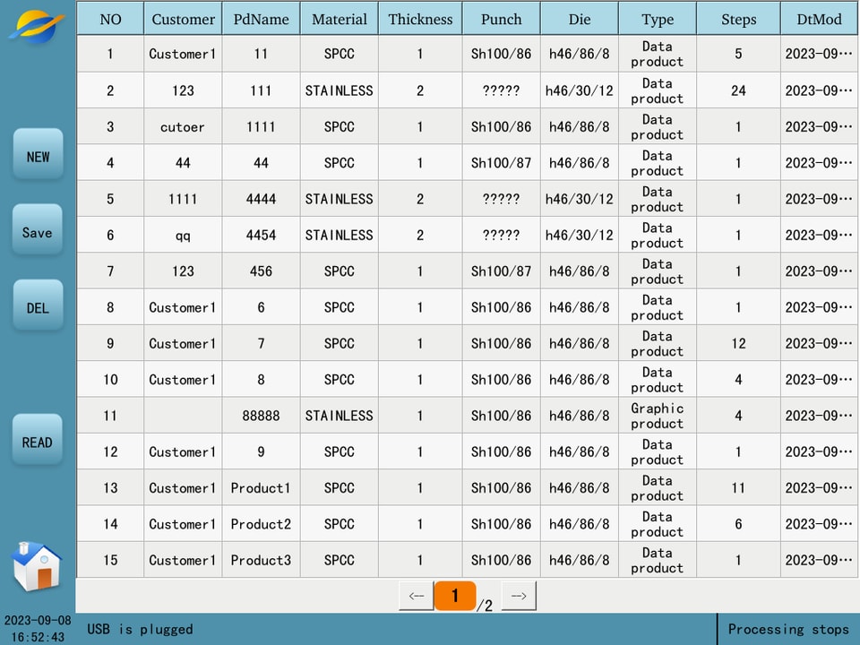
1.Click the "New" button to automatically jump to the"Processing" screen, where you can edit blank product
2.Click the "Save" button, enter the customer’s name and product namein the pop-up window, and the product information in the "Processing" screen will be saved to the product library.
3.Selecta product and click on the "Delete" button, the product will be deleted from the product library.
4.Selecta product, click on the "Read" button, and the product will be read into the "Processing" screen.
Chapter 3 Free bending work step editor

Punch: Click the Punch name to enter the Punch library to select a mold. Users can create, edit, delete and read molds in the Punch library, please refer to "Chapter 4 Mold Library" for details.
Die: Same as "Punch". The mold parameters set here are the system default mold.
Material: Click on the material name to select the processed material from the material library.
Plate thickness: Edit the material thickness.
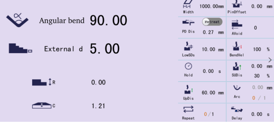
Angle bending: click  can choose "angle bending", "position bending", "flat bending", "bottom bending "way. The back according to the different bending way to enter the corresponding angle or position.
Blocking: Click on to select blocking or palletizing.
Outer Dimension: Click  to select "Outer Dimension", "Inner Dimension", "x- axis position".
R-axis: Input the position of R-axis.
Deflection: Enter the position of the deflection.
Z-axis: input the position of Z-axis center point, since the calculation of Z1, Z2 position; X-axis: The position where the backstop moves horizontally in the vertical mold direction.
Clicking on the number of work steps brings up four buttons for adjusting the work steps, they are:
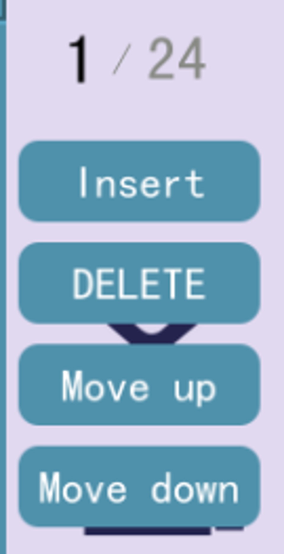
Insert: insert a blank line work step above the current work step.
Delete: delete the current work step, the following work steps are automatically moved up one line.
Upshift: exchange the position of the current work step with the previous work step.
Downshift: exchange the position of the current work step with the next work step.
3.1 Detailed reference
Processing of the right-hand side of the detailed parameters, there is also a left-hand side of the mode selection chapter in detail.
Bending method selection:
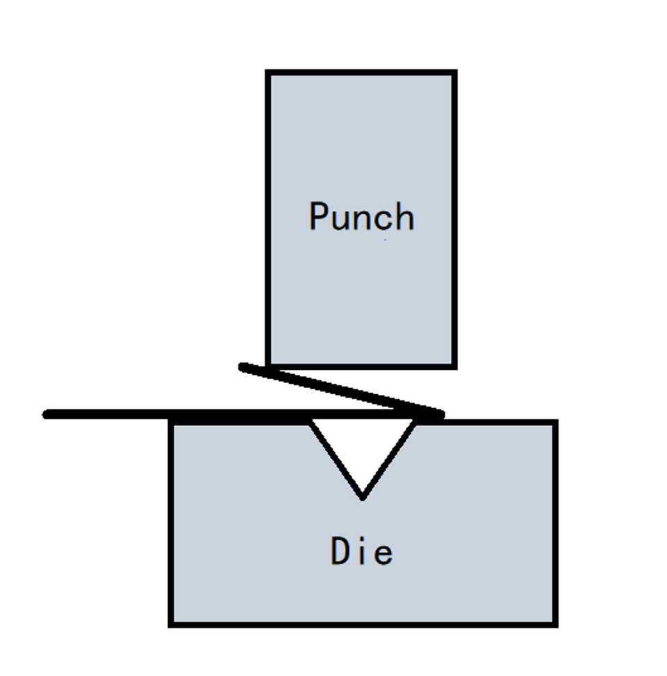
Free bending: The sheet is bent to the set angle by dropping the Punch to the desired depth, as shown in Figure. The system calculates the required Y-axis position to obtain the set angle. Free bending requires the Punch angle to be less than or equal to the Die angle, and the target angle to be larger than both the upper and Die angles.
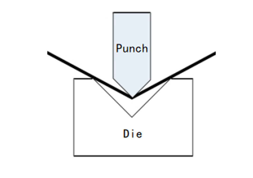
Figure 3-4 Free bending
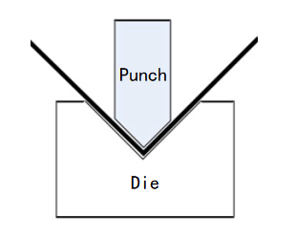
Press bottom bending: The Punch will be folded into the bottom of the Die to get the required bending angle, as shown in Figure. The Y-axis position is the position of the bottom of the Die minus the plate thickness, which can be corrected by the correction value.
Flattening bending: the plate is bent into a sharp angle after the previous bending, using the flattening Punch, the sharp angle of the plate is flattened and the plate is folded, as shown in Figure 3-6 the Y-axis position is for the position of the pressure plate point minus the plate thickness, which can be corrected by the correction value.
Press bottom flattening: like press flattening bending, the Y-axis position is for the position of the press plate point, which can be corrected by the correction value.
Dimensions: inner dimensions, outer dimensions. As shown in Figure.
The distance of the stopper end from the inside of the sheet metal at the bend, called the inner dimension.
The distance of the stopper end from the outer side of the sheet metal at the bend, called the outer dimension.
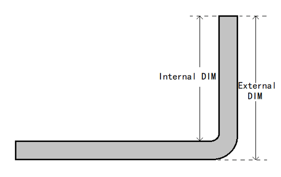
The X-axis target position is calculated differently for the inner and outer dimensions because the inner side shrinks and the outer side extends when the sheet metal is bent. the X-axis target position is larger than the inner dimension and smaller than the outer dimension.
Rear blocking material: blocking and holding material. When the distance of X-axis is short, choose the blocking mode. When the X-axis is long, due to the gravity of the plate material downward tilt can choose the palletizing mode, the plate material will be placed on the
blocking finger forward to hold. When you use the pallet mode, the system automatically calculates the target position of X-axis and R- axis in the pallet mode.
Retreat distance : The relative distance that the X-axis needs to retreat to avoid when the slider descends to the clamping point.
Clamping point: The position where the slider is just pressed against the plate.
Board width: The width of the sheet along the length of the mold.
Repeat: The number of times the current work step needs to be repeated.
Step change signal: When you click to switch to "use", after the Y-axis return stroke is finished, you need to step on the down pedal once before the backstop will start to move to the position set for the next step.
Step change delay: the delay time before switching to the next work step.
Slow distance: The distance between the speed change point and the platen point. If the current work step slow distance is 0, the "default slow distance" is used. If the default slow speed distance is also 0, the system default slow speed distance is used.
Holding time: The holding time after the end of bending. The "default hold time" is used when the hold time of the current work step is 0.
Chapter 4 Mold Library
4.1Punch library
In the "Machining" screen, click on the Punch name to enter the Punch library screen, as shown in Figure.
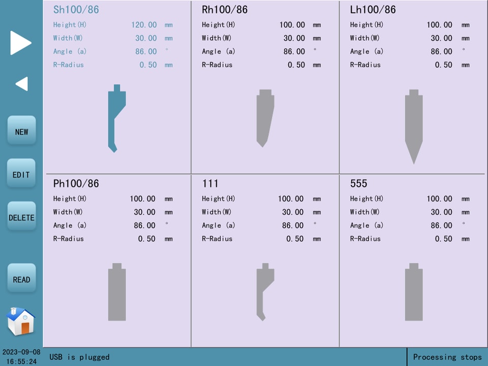
The Top Model Library shows the list of top models saved in the system, which can be turned by the left arrow.
Click on the menu bar pop-up button.
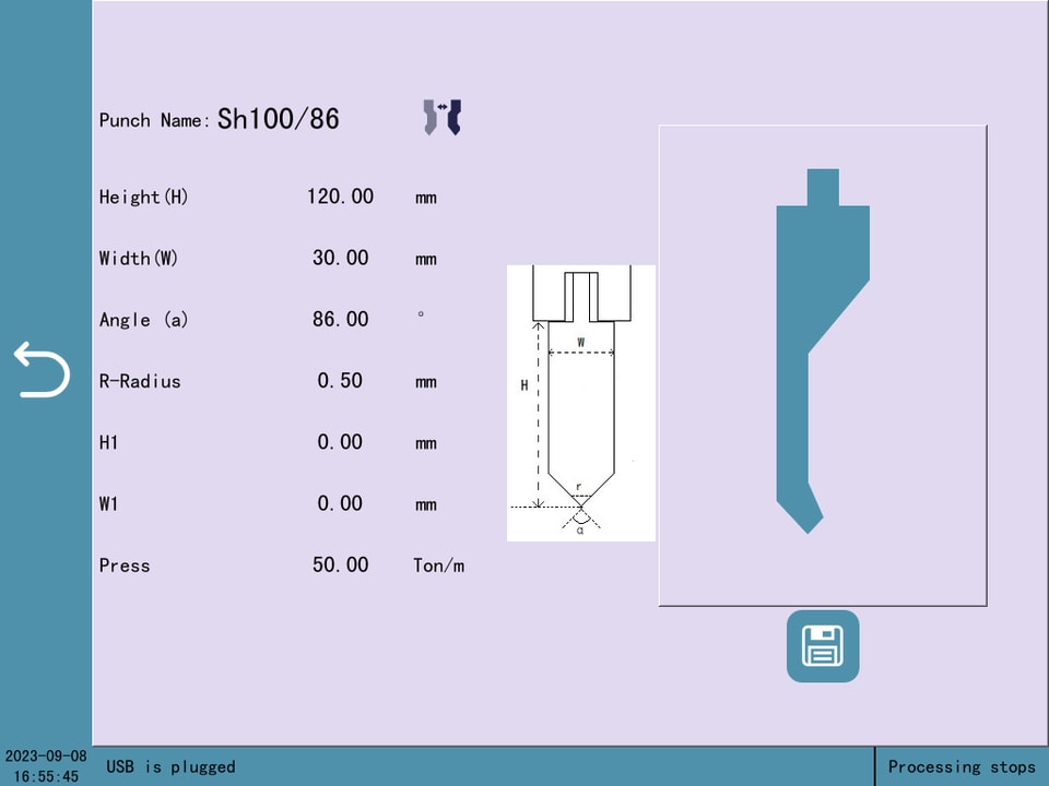
New Click "New" to bring up various types of new Punchs; enter the editing interface as shown in Figure.
Edit : Click "Edit" to modify a parameter of the current Punch.
Delete : Select a Punch and click "Delete" to delete the Punch.
Read : Select a Punch and click "Read" to read the selected Punch into the current application.
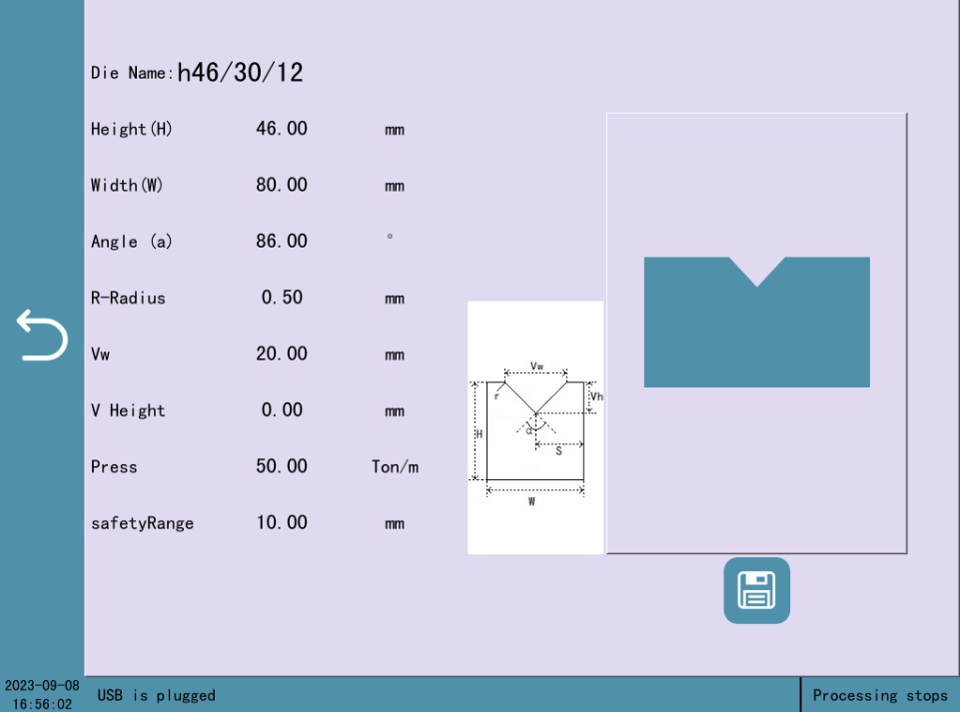
4.2 Die library
Chapter 5 System
5.1Alarm troubleshooting
Serial number | Alarm description | Alarm Checking |
Err1 | Motor not on | Click the START button or motor button to turn on the motor |
Err2 | Reaching the limit | Enter the single-step screen, move in the opposite direction by inching and leave the limiter |
Err3 | Both ends produce limits simultaneously | Check if the limiter is damaged or if there is an open circuit in the line |
Err4 | Wrong axis target position setting | Check if the target position is set to check the upper and lower limit range |
Err5 | No valid line found | There is an error in the current work step parameter input |
Err7 | Before action, please seek reference | Enter the status screen, click on the search button and wait for the search to complete. |
Err14 | Y-axis tilt | Enter the single-step screen, inching or hand cranking the wheel to level the slider |
Err16 | Emergency stop button is pressed | Release the emergency stop button |
Err17 | Emergency rise button is pressed | Release the emergency rise button |
Err21 | Wrong setting of backstop position | Risk of collision with backstop material, check set-up parameters |
Err30 | IO card communication offline | Re-plug the communication cable between PLC and IO |
Err34 | Reaching the soft limit | Enter the single-step screen, inching in the opposite direction of movement |
Err38 | Security Monitoring | Check drive for alarms |
Contact Us