-
tel:
+86-13222111178 -
email:
info@ntjugao.com


CNC Press Brake with T8 CNC Controller: Installation and Operation Guide
CNC Press Brake with T8 CNC Controller: Installation and Operation Guide
Jun 23, 2025
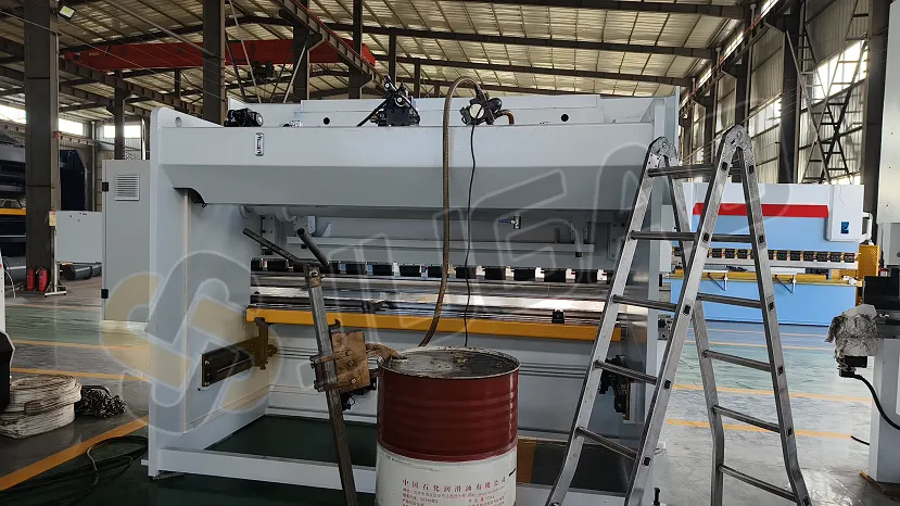
1.Hydraulic Oil Filling
●Oil Selection: Use anti-wear hydraulic oil suitable for ambient temperatures. For standard conditions, 46# anti-wear hydraulic oilis recommended.
●Oil Volume: Fill the tank to 80%-90% capacity.
Key Steps:
●0:31: Connect the foot pedal switch by aligning the aviation connector’s bayonet and tightening its nuts.
●0:53: Connect the power cable based on the machine’s total power. Attach the three-phase wires to the electrical cabinet’s power switch.
●1:37: Turn on the electrical cabinet’s power switch.
●1:57: Verify all emergency stop buttons are released.
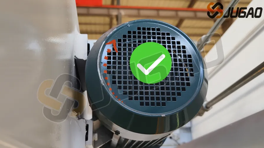
●2:07: Start the oil pump via the screen button, then press the emergency stop. Confirm the main motor rotates clockwise(check the motor’s direction sticker).
○If counterclockwise, swap two phase wires and retest.
2. Machine Leveling
3:13: Use a spirit level to measure the worktable’s horizontal accuracy. Adjust the base plate bolts (place steel plates underneath for stability).
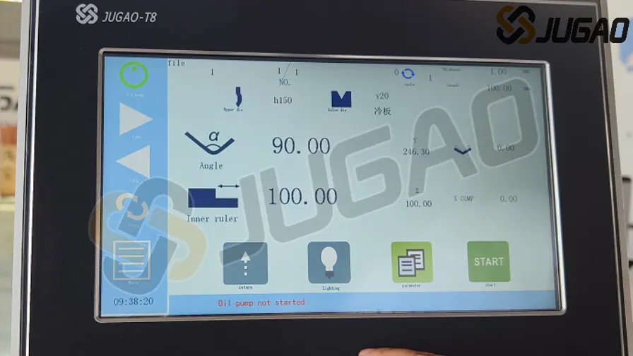
3. T8 System Interface Functions
●3:37: Oil Pump Control: Hold for 3 seconds to start/stop the motor.
●3:43: Upper Die Selection/Editing: Match the library to actual tools.
●3:48: Lower Die V-Groove Editing: Input actual groove sizes (e.g., 8× sheet thickness).
●3:55: Material Thickness/Length Input: Enter measured values.
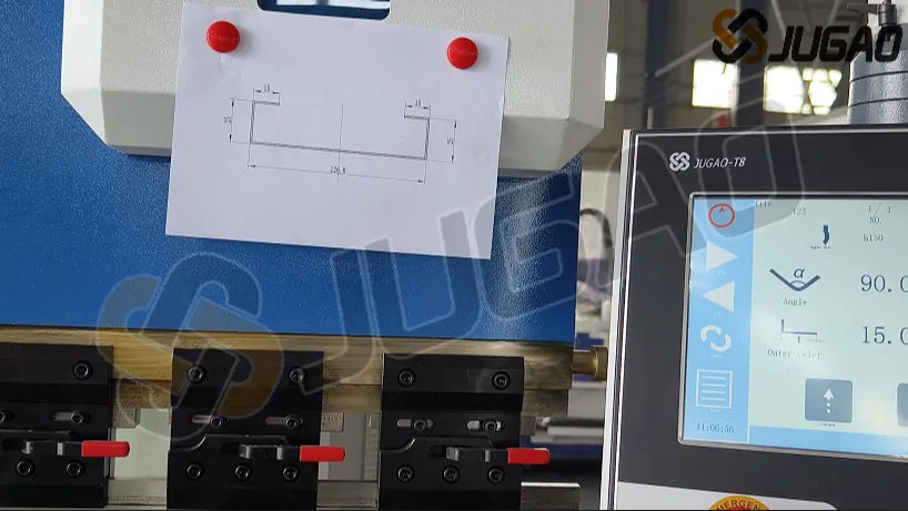
●4:03: Angle Display Toggle: Switch between bend angle and Y-axis value.
●4:07: Bend Angle Setting: Input desired angle (e.g., 90°).
●4:12: Angle Correction: Compensate deviations (e.g., enter –1.5° for a 91.5° result).
●4:19: X-Axis (Backgauge) Control: Set positions for internal/external dimensions.
●4:30: Slider Return: Move to upper dead center.
●4:38: Program Execution: Press "START"; displays "STOP" during operation, "OK" when complete.
●4:48: Pressure Delay: Set to 3.0–5.0 sec for optimal bending.
Operational Modes:
1.Inch Mode: Foot pedal controls incremental movements.
2.Single Cycle: Completes full bend cycle (fast/slow descent + pressure).
3.Continuous Mode: For testing (not production).
4. Tooling Setup
●6:28: Upper Die Selection: Measure and input actual height.
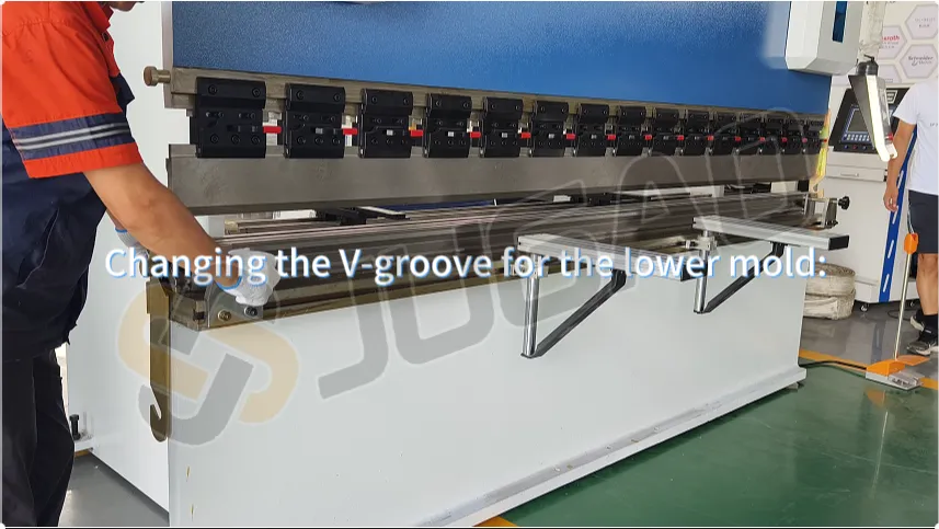
●7:14: Lower Die V-Groove:
○Rule: Groove width = 8× material thickness (e.g., 8mm for 1mm sheet).
○Replacement: Loosen screws, flip the die, and align the new groove with the upper blade.
5. Calibration & Testing
●14:15: Angle Calibration:
○Test bend (e.g., 1mm iron plate, 90° target).
○If error >5°: Manually adjust Y-axis (password: 0313), fine-tune in 0.5–1.0 increments.
●15:52: X-Axis Calibration: Compensate measured dimensional errors.
●17:47: Program Validation: Check each bend against drawings; save after alignment.
●22:47: Synchronizing Left/Right Angles:
○Adjust the sync shaft behind the slider (rotate 5 turns/test until angles match).
6. Pressure Adjustment & Alarms
●26:21: System Pressure: Adjust the remote valve clockwise while pressurized.
●Common Alarms:
○Oil Pump Not Started: Press the start button.
○Slider Not at Top: Return to upper position before operations.
○Servo Alarm: Check for mechanical obstructions (consult JUGAO if unresolved).
Conclusion
This guide covers installation, calibration, and troubleshooting for the T8-controlled CNC press brake. For advanced support, contact JUGAO Technical Services.
Pro Tip: Always verify tooling dimensions and system settings before production runs.


Recent Posts

October 26, 2016
The Most Successful Engineering Contractor
Apr 16, 2026
Replacement Frequency of Welding Robot Contact Tips

Apr 16, 2026
Rotational Degrees of Freedom in Welding Robots


Contact US
Product Information
Quantity
Unit
Piece
Support order samples, customization, wholesale direct, and complete payment. If the product you look for does not have corresponding customized content, pls fill out the form below to contact us, and we will reply ASAP.