
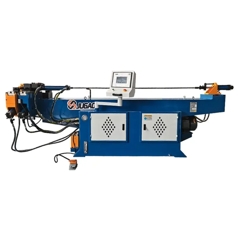
CNC pipe bending machine servo motor alarm? Don't panic, follow this troubleshooting method and you'll likely fix it.
2026-05-27

Anyone who works with pipe bending machines knows that the biggest problem with CNC models is the servo motor alarm. A string of codes on the screen means the machine is grounded, and the entire project is delayed. This sounds scary, but it actually boils down to problems in three areas: "mechanical load, electrical wiring, and parameter settings." Below, I've compiled my experience over the years, explaining each alarm type in turn.
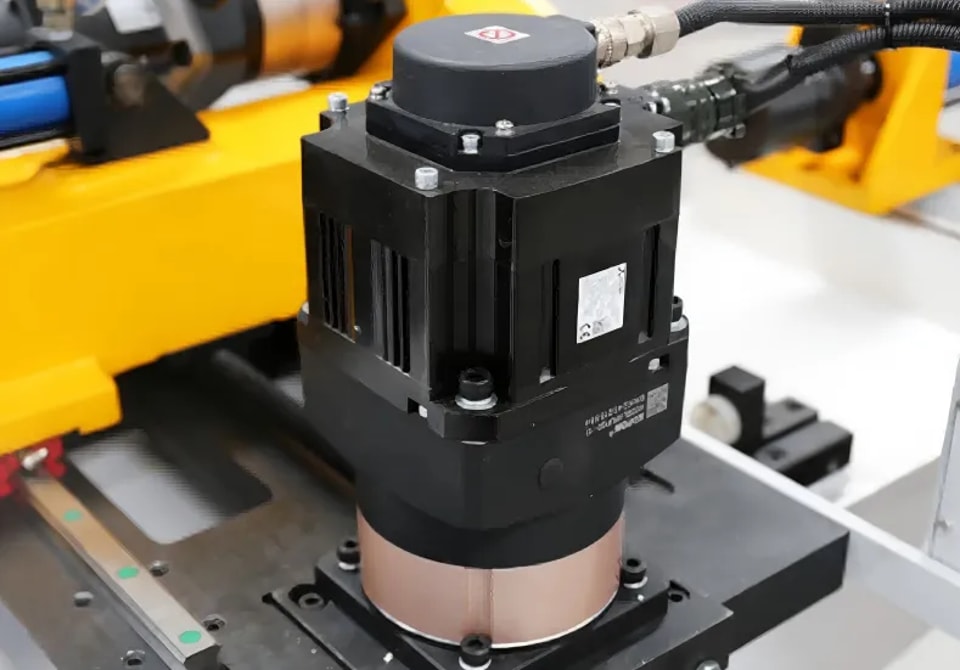
Step 1: When an alarm occurs, write down the code.
Alarm codes are like the equipment's "medical record"; writing them down incorrectly is like prescribing the wrong medicine. Regardless of the brand of the system, be sure to record the complete alarm code on the screen, the fault description, and the operating conditions at the time of the incident (e.g., which pipe is being bent, what material it is). Different systems have different characteristics: FANUC commonly reports "SRVO-414" servo overload, Siemens often reports "25201" contour monitoring, and Mitsubishi has codes such as "AL.E6" and "AL.16". Writing down the code is the first step; you can find it in the manual or by searching online.
Step 2: Overload Alarm (most common, accounting for 60-70%)
If the motor surface is very hot and the driver displays codes like "OL" or "AL.50", it is most likely an overload. The cause is mostly mechanical: insufficient lubrication of the guide rail, stuck lead screw, too tight timing belt, or misalignment of the mold. Rotate the shaft by hand to feel the resistance. Another possibility is that the acceleration/deceleration time is set too short, causing the motor to experience excessive instantaneous current, which is mistakenly interpreted as an overload. Solution: First, check the lubrication of the transmission components, then try appropriately increasing the acceleration/deceleration time in the driver parameters.
Step 3: Encoder Alarm (Angle Accuracy Depends on It)
If the driver reports "AL.16" (Mitsubishi), "Encoder Error," or "25000" (Siemens), or if the angle is off-center or the motor vibrates excessively, it's basically a problem with the encoder link. This usually occurs in these areas: loose encoder connectors or water/oil ingress, damaged shielding wires, or internal cable breaks at bends. Delta servo drives are particularly prone to problems, especially the rectifier bridge and encoder feedback loop. You can directly connect a resistor in parallel to test if the feedback is normal. Solution: Re-plug and clean the connectors, and check for bends or damage to the cable. When troubleshooting this type of fault, pay attention to distinguishing between software and hardware issues; the process of elimination is the most reliable way to locate the fault.
Step 4: Power Supply Voltage or Wiring Issues
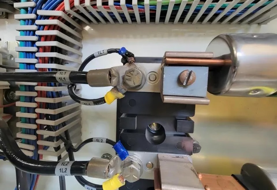
If the device alarms immediately upon power-on, or the motor doesn't respond at all, check the power supply first. Use a multimeter to measure the input voltage (fluctuations should be within ±10%), check if the driver's DC bus voltage is up to standard, and confirm if the circuit breaker has tripped. When multiple servo drives alarm simultaneously, it's highly likely that the main power supply is experiencing a phase loss or undervoltage. If only a single axis alarms, focus on checking the power lines (U, V, W) and encoder lines of that axis, checking for water ingress into the connectors and bent pins.
Step 5: Communication Failure
If the screen displays "AL.E6" (Mitsubishi) or "AL.16" communication error, it's mostly due to poor wiring contact or missing parameters. Troubleshooting: Unplug and re-tighten the communication cable, restore the backup PLC program, and verify the station number and baud rate settings in the driver. If interference is severe, shielded cables must be used for the signal lines, and the shielding layer must be grounded at one end of the driver. Cable securing is also crucial; the cable should be firmly fixed to a stationary location to minimize bending stress.
Step 6: Alarms Caused by Limit Switches or Interference
An alarm may be triggered if a shaft presses against a hard limit switch, there is a collision between mechanical parts, or the safety door is not properly closed. First, visually check the position of each shaft. If it is pressing against a limit switch, move it in the opposite direction to disengage it; if it is not pressing against a limit switch, check if the signal of the limit switch itself is normal.
Practical Troubleshooting Sequence (Start with the Most Possible):
① Power off for 5 minutes and then restart: Some false alarms will disappear automatically.
② Check the power supply and emergency stop circuit: Phase loss or emergency stop errors are a large proportion of false alarms.
③ Confirm the encoder and power lines: Unplug and plug the connectors to measure continuity.
④ Eliminate mechanical load and lubrication issues: Manually rotate the engine to check for any jamming.
⑤ Verify the driver parameter settings: Pay close attention to acceleration/deceleration times, electronic gear ratios, and torque limit values.
⑥ Exchange spare parts for verification: Swap drivers or motors of the same model to quickly locate hardware faults.
A core troubleshooting logic: If the alarm persists after removing a servo axis, the fault of that servo axis can generally be ruled out. Continue using this method to remove other servo axes until the alarm disappears. This pinpoints the fault to a specific axis, allowing you to then use the previously described methods to check the axis's driver, encoder, motor, cables, and external factors.
Routine Maintenance and Alarm Prevention Habits
Check the motor cooling fan monthly and clean surface dust; every six months, when shutting down, wipe the inside of the electrical cabinet with a cloth and clean the encoder connectors; open the driver housing and use a vacuum cleaner or soft brush to remove dust from the circuit board—industrial environments are complex, and many alarms are caused by short circuits due to accumulated dust. During routine inspections, check the motor temperature and cooling fan for normal operation, and occasionally use diagnostic software to check the load rate to keep track of the situation. Additionally, never use a hammer to directly strike the servo motor shaft to install or remove the coupling, as this will damage the precision encoder on the other end of the motor.
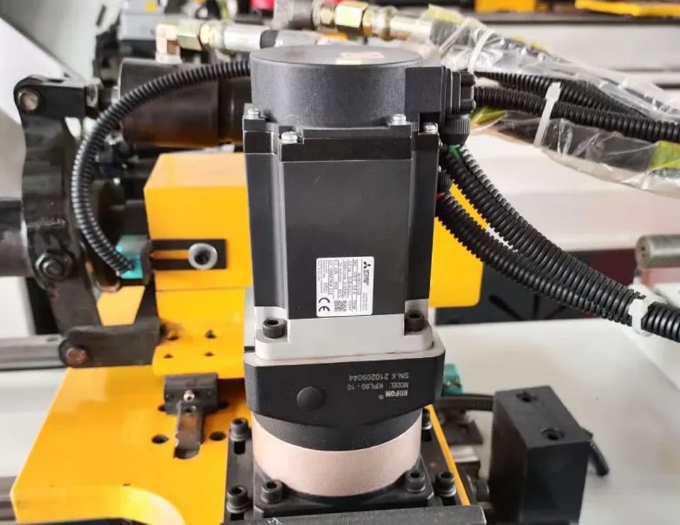
Servo alarms on CNC pipe bending machines are not a cause for alarm. As long as you follow a troubleshooting approach of "recording the code → examining the machine's feel → measuring the main circuit voltage → checking the encoder feedback cable → verifying system parameters," the root cause of most alarms can be identified within 30 minutes.
Contact Us